MEMS Module
New App: MEMS Pressure Sensor Drift Due to Hygroscopic Swelling
For their integration in microelectronic circuits, MEMS devices are bonded on printed circuit boards and connected with other devices. Then, the whole circuit is often covered with an epoxy mold compound (EMC) to protect the devices and their interconnects with the board. The epoxy polymers used for such applications are subject to moisture absorption and hygroscopic swelling, which can lead to delamination between the EMC and the board or to incorrect behavior of MEMS components.
The MEMS Pressure Sensor Drift app simulates the drift of the measured strain over time due to hygroscopic swelling on a MEMS pressure sensor subject to a moist environment. The app helps the designer to reach the required sensitivity and minimize the drift. This is done by specifying geometrical parameters, mold compound material properties, and external conditions.
The app was built utilizing the Transport of Diluted Species, Solid Mechanics, and Shell interfaces in the COMSOL Multiphysics® software.
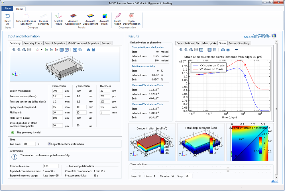 The MEMS Pressure Sensor Drift Due to Hygroscopic Swelling app, showing results from a simulation of pressure sensor stability.
Material Models from Externally Programmed Libraries
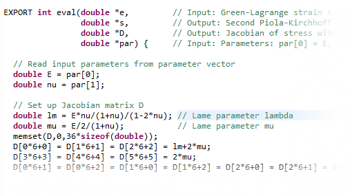
A new way to specify user-defined material models is included in COMSOL Multiphysics version 5.2. You can now access external material functions, written in C code, which have been compiled into a shared library. By writing a gateway function in C code, you can also use material functions written in another programming language. This makes it possible to program your own material models and distribute such models as add-ons.
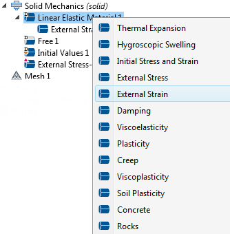
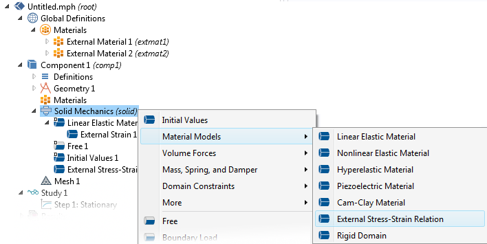 Add an External Stress-Strain Relation as the material for some domains.
The external library can either completely define the stress-strain relation, or only return an inelastic strain contribution to the available material models. Using only an inelastic strain contribution is quite powerful in itself. It allows for the implementation of materials similar to the built-in material models available as subnodes under the Linear Elastic Material node; for example, plasticity and creep. The complete stress-strain relation, on the other hand, corresponds with a top-level material node, such as the Cam-Clay material model, and is used to define a material model from the ground up.
Two new features are available in the Solid Mechanics interface to accommodate this new functionality: the External Stress-Strain Relation material model and the External Strain subnode under the Linear Elastic Material node.
The existing user-defined options in the Hyperelastic Material, Plasticity, and Creep nodes, for example, provide a convenient, but more limited way of defining your own material models.
Contact with Small Relative Displacements
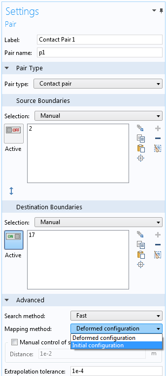
COMSOL Multiphysics version 5.2 introduces a new, simplified method for computing the distances within contact pairs. You can use this functionality when there is little sliding between the contacting surfaces, such as in a shrink fit or when two parts are bolted together. In this method, the mapping between the source and destination is computed only once, which leads to faster and more stable convergence. To use this method, set the mapping method to Initial configuration in the settings window for the contact pair.
Initial Contact Gap Adjustment
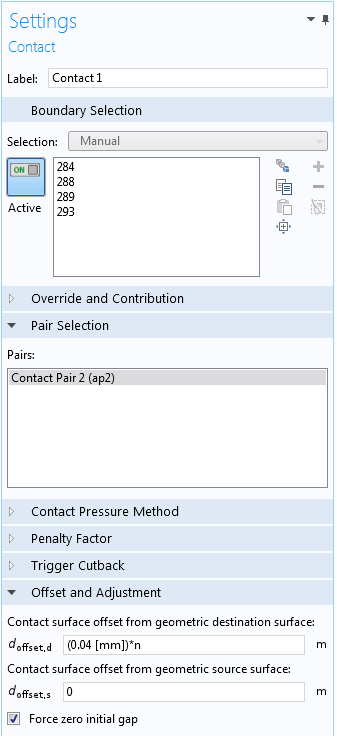
Sometimes, the finite element discretization of curved boundaries causes the initial distance between the two boundaries in a contact pair to have noticeable irregularities. You can now compensate for this issue through a built-in computation of the initial gap. This initial gap can then be subtracted in the subsequent analysis if you select the Force zero initial gap check box in the Contact settings window in the Solid Mechanics interface.
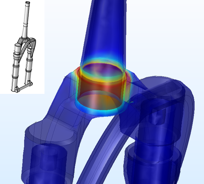 Stresses caused by the shrink fit between the steering tube and crown in a bike fork (from the new Interference Fit Connection in a Mountain Bike Fork tutorial).
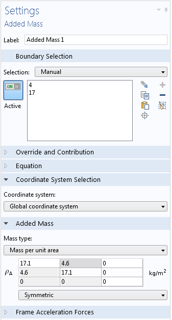
Full Mass Matrix Input in Added Mass
The Added Mass feature has been extended so that it is possible to enter a full mass matrix.
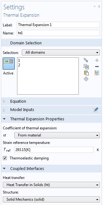
Optional Inclusion of Thermoelastic Damping
In the Thermal Expansion multiphysics coupling, you can now select whether or not the time derivative of the stresses should act as a heat source in the heat transfer problem. By selecting the new Thermoelastic damping check box, the problem will become two-way coupled when a time-dependent problem is solved.
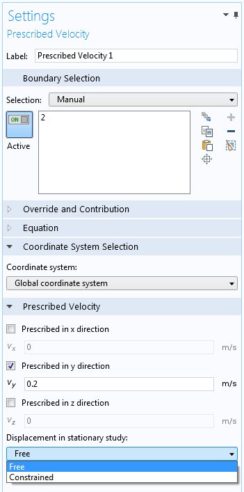
Prescribed Velocity/Acceleration Interpretation in Stationary Analysis
When the Prescribed Velocity or Prescribed Acceleration nodes are present in your model, you can define how these boundary conditions should be interpreted in a stationary analysis. They can either be treated as a constraint (constrained), or ignored (free). This is particularly useful in models and apps with multiple mixed-analysis types, including frequency-domain, time-dependent, and stationary types.