How to Select Geometry
There are many points during the model building process wherein you will need to make selections of the geometry in your model. In COMSOL Multiphysics®, there are many tools, features, and functionality that enable you to make these selections efficiently. This article shows you how to select geometry using various methods.
Basic Geometry Selections
Watch and follow along to the first video with the exercise file, which covers the following:
- The mouse in the Graphics window to select simple geometries or individual entities
- The mouse scroll-wheel button to reach interior geometric entities
- The Graphics window toolbar to select multiple entities quickly
- The Selection List window to use for complex geometries
- The Settings window toolbar to copy and paste lists of geometric entities from one node's settings to another
- Preselections to add physics nodes from the ribbon
Graphics Window Context Menu
There is further functionality available through the Graphics window for you to both make a selection of a model geometry and then apply settings to the selection. This is done through the Graphics window context menus. It enables you to simply and easily add features or operations to the geometry you have preselected. Creating a selection of the geometry and then accessing and using the Graphics window context menu involves the following steps:
- Right-click in the Graphics window and initialize a new selection
- Select the desired geometric entities
- Right-click in the Graphics window again to access a context menu of choices and make your selection
This method streamlines and simplifies selections and is available alongside the selection methods aforementioned at the start of the article and in the tutorial video. The Graphics window context menus are available when working in many of the modeling workflow steps, including definitions, geometry, meshing, materials, and physics.
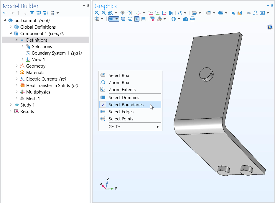
Right-clicking in the Graphics window presents a menu through which you can initialize a new selection.
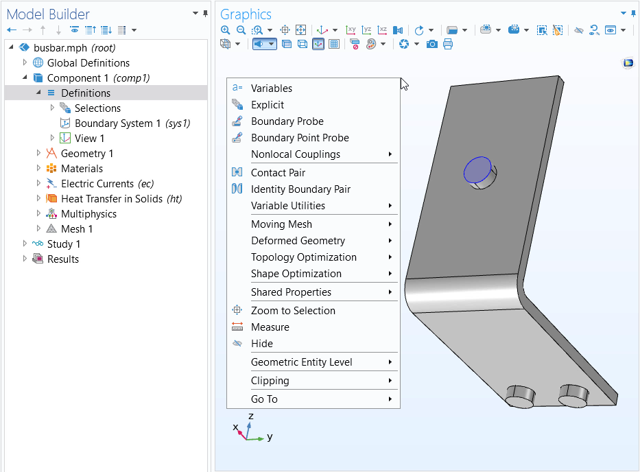
After selecting the geometry (in this case a boundary), right-clicking once again in the Graphics window presents a context menu for adding Definitions features, such as probes, to the selection.
Identify Geometric Entities with Geometry Labels
It can be useful to know the numbering for all the geometric entities in your model as well as display the numbers over their respective parts right within the Graphics window. This enables you to be sure of exactly what parts of the geometry you are choosing and confirm your selection. Watch the video below and follow along with your own model, or the Electrical Heating in a Busbar model in the Application Libraries. Functionality shown in this video includes:
- The Selection List window, which displays a list of the geometry labels based on the geometric entity level button selected in the Graphics window
- The Show geometry labels check box, which displays the numbering of all of your model's geometric entities in the Graphics window
As of COMSOL Multiphysics® 6.0, you can hover your mouse over geometry in the Graphics window and the associated geometry label will automatically be displayed on the left side of the Graphics window. When working with geometries, the label of the geometry object will be displayed instead of the domain, boundary, edge, or point number. You may disable this functionality with the Show information on hover check box in the Graphics Interaction page found with the Preferences dialog box.
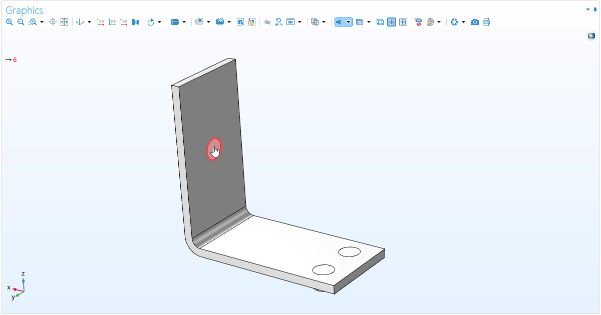 Hovering Over a Titanium Bolt
The geometry label for the geometric entity which the cursor is hovering over is shown in red text.
Hovering Over a Titanium Bolt
The geometry label for the geometric entity which the cursor is hovering over is shown in red text.
Geometric Entity Color Display Based on Selection Status
You will notice that in the Graphics window, the color displayed on the selected geometry changes. The color displayed on the geometric entities in your model indicates their selection status for whatever node you have currently selected. This provides you with an interactive visual display of what geometry is added, removed, already included, or omitted from a selection for any modeling feature, tool, or operation.
Hiding or Showing Geometric Entities
Sometimes, when you’re displaying a geometry in 3D, you might have to hide a boundary or even a whole domain to get a good look at what’s going on inside, especially in cases where wireframe rendering is not an option. A common example of this is a complex model geometry with an air domain around it — the air is usually represented by a finite box. Chances are, you don’t want to see the box when you set up your results.
At other times, you may want a view that displays the inner parts of a component’s geometry. The COMSOL Multiphysics® graphics tools offer several ways to hide parts of a model. We’ll continue using the View node, where you can choose to hide objects or entities.
Start by creating a new View node by right-clicking the Definitions node and then selecting View. Then, right-click the newly added View node, and choose the Hide for Geometry option.
Note: The Hide for Geometry option hides geometry objects or geometric entities created by a geometry feature. It is only available under the Geometry node and affects the view in the Geometry, Materials, Physics Interface, Mesh, Study, and Results branches.
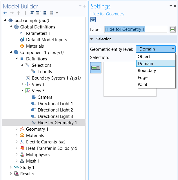
The Hide for Geometry node and Settings window.
As an example, let’s take another look at the busbar model. Suppose you want to hide one of the side faces and the top face of the horizontal extrusion so that you can see the bolts inside. For this, pick Boundary as the geometric entity level. Click on each of the faces you want to hide to select them (they’ll turn blue). If you click the View node again, you’ll still see the model, but your chosen boundaries are now invisible.
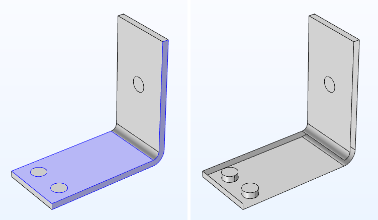
View of the geometry before (left) and after (right) the Hide for Geometry feature is applied to the selected boundaries.
If you want your results to show this view, select the plot group you want to apply it to. Under Plot Settings (below), select the view you’ve been working in (this is View 5 in our example), which will cause the plot results to update.
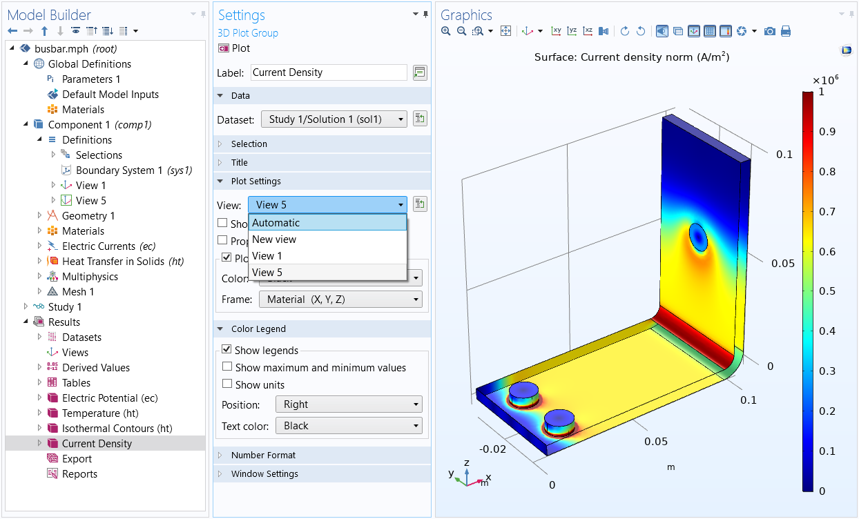 Options for the view to display in the Plot Group node's Settings window.
In the view above, only boundaries have been hidden, but we could have also hidden other geometric entities such as domains, edges, and even points! To do so, however, you need to create additional Hide for Geometry nodes, since you can't select more than one type of entity to hide in a single node. Watch the video below and follow along with your own model, or the Electrical Heating in a Busbar model in the Application Libraries, to learn how the geometric entity color displays changes as you select geometry and what the highlighted color displays mean.
Hiding and Showing Video Example
Hiding and showing is further featured in the video below and includes the following functions:
- Hiding and Showing Geometric Entities buttons in the Graphics toolbar, which you can use to choose what geometry to hide and then toggle between seeing the hidden and unhidden geometric entities in your model
- Hide for Geometry feature, which you can use to customize what parts of the geometry are hidden when working under the Geometry node
- Hide for Physics feature, which you can use to customize what parts of the geometry are hidden when working under the Materials, Physics, Mesh, Study, and Results nodes
Follow along with your own model, or the Electrical Heating in a Busbar model in the Application Libraries, to learn how to show or hide parts of the geometry in your model.
Named Selections
Now that you have learned the many ways and tools you can use to select geometry in the software, you can create groups of these selected geometric entities that you can reuse throughout your model setup. We refer to these groups of selected entities as named selections. An example would be grouping the relevant selections together and naming them Inlet. During your modeling process you may then simply select the Inlet as a whole and apply materials, physics, etc. There are a few more selection tools to help you create named selections, which are covered with their own videos. They are as follows:
Submit feedback about this page or contact support here.