3D-model of an AC/DC Hybrid EHV Transmission Line to Analyze the Electrical Field along Insulators
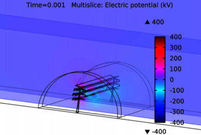
To increase the power transfer capacity of existing lines, a transmission system operator in Germany plans to replace an existing 380-kV three-phase AC system into a bipolar HVDC system on the same tower that is called a 'hybrid line'. Due to the proximity of AC transmission systems and the HVDC system electrical and magnetic coupling effects between those lines are present during system operation. The mutual influence of the electromagnetic fields between the AC and DC systems can cause changes in electrical components. The electrical performance of a composite insulator is affected by the electrical field distribution along its length and surface. The calculation of the electric field distribution is very important for the design of EHV transmission lines. The insulators are an important part of the transmission lines to prevent tripping of the transmission line by a flashover over the insulator. The electrical field distribution around the composite insulators and the heads of transmission towers is numerical calculated using finite element method. The calculations were executed in the time domain. A three-dimensional (3D) model of a hybrid transmission line for a given tower configuration has been developed and the model is presented in this paper. The geometric dimensions and material properties of an insulator are taken into consideration. In this paper a field calculation program called COMSOL Multiphysics® is used. COMSOL Multiphysics® is a powerful simulation software that uses finite element method (FEM) to simulate multi-field problems. The electrical field distribution around three 380-kV AC systems and one 400-kV bipolar DC system is analyzed. In this paper, the Electric Currents interface is used.
Download
- potkrajac_poster.pdf - 0.91MB
- potkrajac_paper.pdf - 1.33MB
- potkrajac_abstract.pdf - 0.01MB