support@comsol.com
Pipe Flow Module Updates
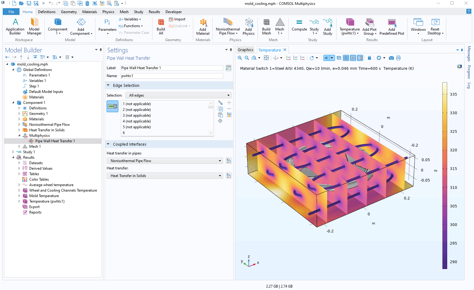
For users of the Pipe Flow Module, COMSOL Multiphysics® version 6.1 introduces a new multiphysics coupling to account for the heat exchange through a pipe wall, new parameterized geometries in the Part Library, and enhancements for mechanical piping analyses. Learn more about these updates below.
Pipe Wall Heat Transfer
There is a new Pipe Wall Heat Transfer multiphysics coupling available for connecting:
- Domains that are modeled using the Heat Transfer interfaces
- Edges modeled using the Heat Transfer in Pipes interface or the Nonisothermal Pipe Flow interface
The existing Cooling of an Injection Mold and Ground Heat Recovery for Radiant Floor Heating models showcase this new feature.
Library of Pipe Geometries
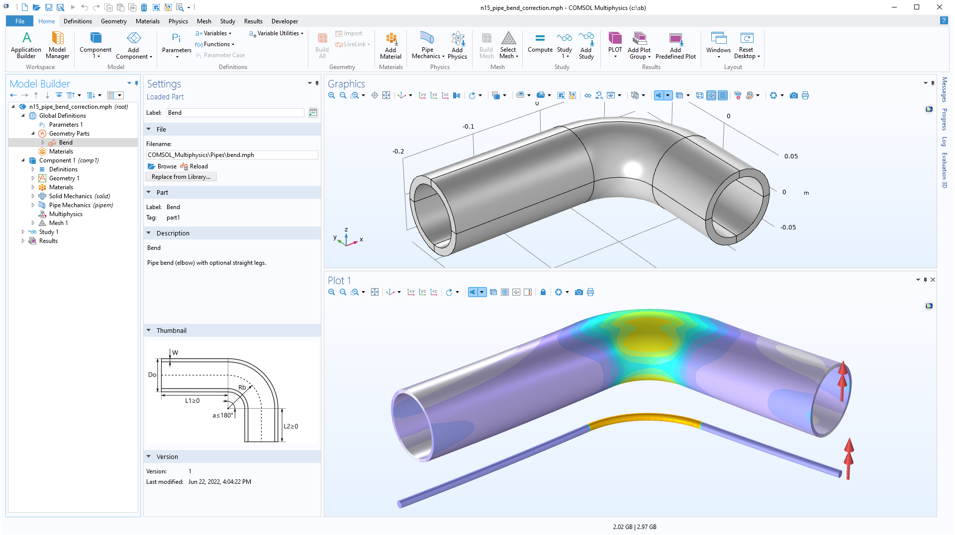
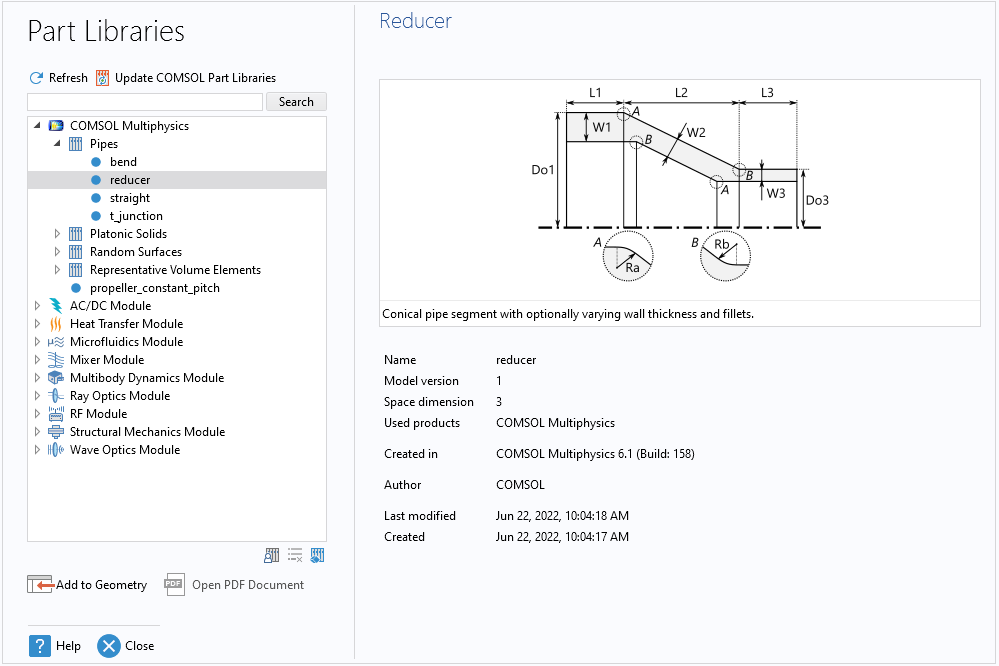
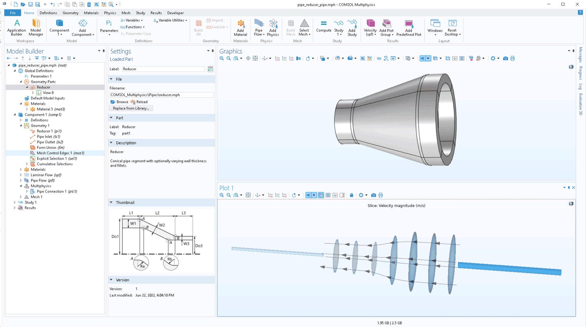
In the part libraries, a number of parameterized geometries for pipes have been added: straight, bend, reducer, and t-junction. These geometries can, for example, be used for detailed analysis using the Fluid Flow or Structural Mechanics interfaces. Such 3D models can be directly connected to the Pipe Flow interface or Pipe Mechanics interface through the Pipe Connection or Structure-Pipe Connection multiphysics couplings.
Mechanical Piping Analysis Enhancements
For the analysis of pipes, the following updates are available:
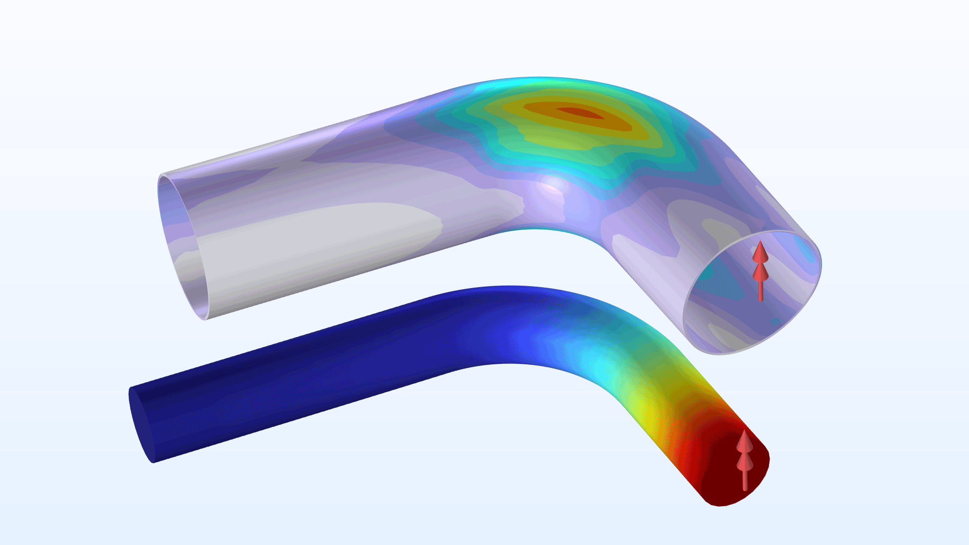
- In the Pipe Mechanics interface, you can now specify correction factors for flexibility and stresses in pipe bends.
- You can now enter a reduced wall thickness for stress evaluation. This is used, for example, to take a corrosion allowance into account.