Multibody Dynamics Module Updates
For users of the Multibody Dynamics Module, COMSOL Multiphysics® version 5.4 includes fluid-structure interaction for assemblies, flexible attachments, and reference frames to assist postprocessing. Read more about these multibody dynamics features below.
Fluid-Structure Interaction for Assemblies
The Fluid-Structure Interaction multiphysics coupling has been extended to include the interaction between fluids and multibody systems, making it possible to study problems where a mechanism interacts with a fluid. Since most multibody systems are built as assemblies, this includes a new type of coupling where the mesh on the solid body can slide with respect to the mesh in the fluid domain.
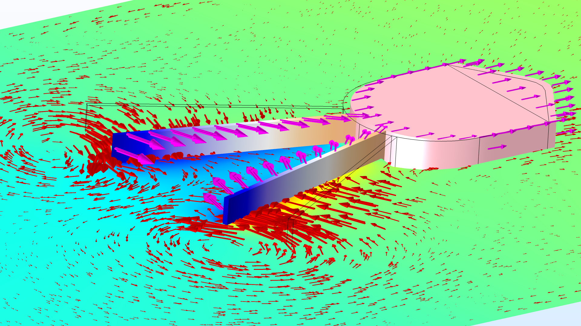
The closing motion and fluid-induced forward motion of a mechanism submerged in a fluid. Magenta arrows show structural velocities, red arrows show fluid velocities, the fluid surface is colored by pressure, and the mechanism surface is colored by displacement.
Flexible Attachments
The Attachment feature has been upgraded with a new Flexible formulation. By enabling it, you can avoid artificial stiffening and spurious stresses at the boundaries where the attachment is connected. With the new formulation, the boundary is allowed to deform and the constraint is applied in an average sense while maintaining force and moment equilibrium.
You can find this feature utilized in the following models:

Comparison of the local stress state close to a hinge joint when using either a rigid or a flexible attachment.
Rolling Element Bearing
Models for six types of rolling element bearings have been added to the Multibody Dynamics interface, enabling high-fidelity modeling of bearing-supported rotating bodies. Each of the bearings can have either a single row or a double row of rolling elements. The bearing model includes a nonlinear representation of the contact stiffness between the rolling elements and the inner and outer races. Note that a Rotordynamics Module license is required to use this feature.
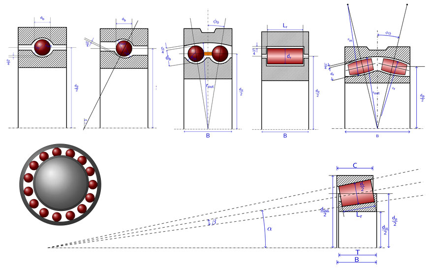
Sketches of different bearing types and their geometrical parameters.
Reference Frames for Results Presentation
In a multibody dynamics model, you often want to plot results, such as displacements or velocities, in a coordinate system that is relative to a moving part. This is now possible by selecting a Body defining reference frame in the new Results section of the Multibody Dynamics node. You can select any Rigid Domain, Attachment, or Gear feature as the body to define the reference frame.
This feature is utilized in the following models:
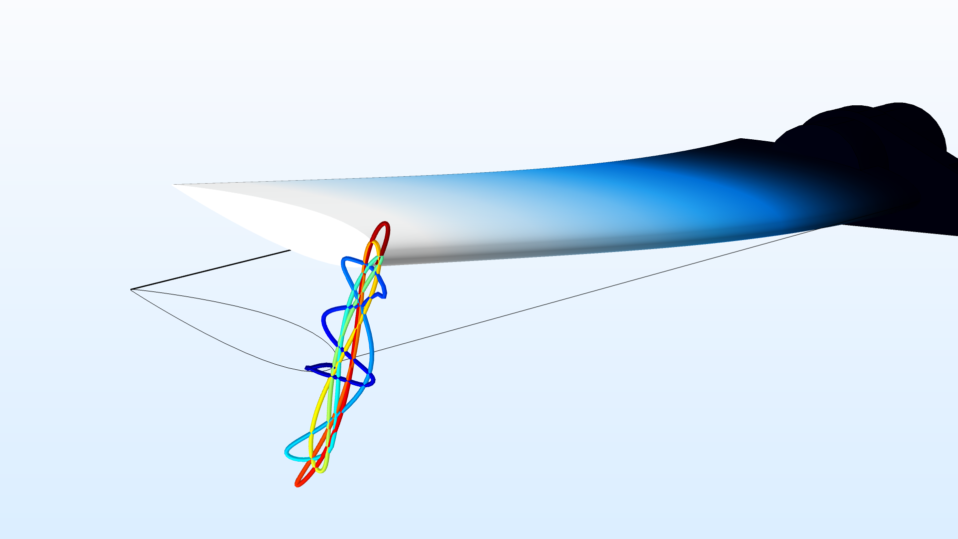
Trajectory of the tip of a helicopter rotor blade, when represented in a frame corotating with the blade attachment.
Roller Condition with Analytical Normal Orientation
In the Roller boundary condition, you can now specify an analytical surface on which the structure slides. It is thereby possible to use the roller condition for finite displacements and rotations. This new functionality can also be used to avoid situations where the normals to a boundary do not have a perfect orientation, something that can happen with imported meshes, for example.
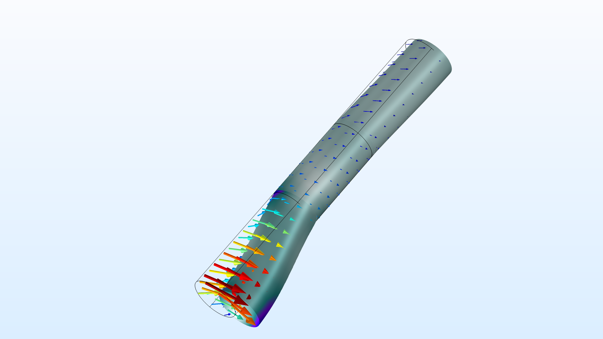
A roller condition defined as a cylindrical surface is used on the middle section of the bar, which is then free to rotate around its axis and to translate axially.
Roller Force Distribution
In the Radial Roller Bearing feature, the contact force distribution is computed accurately using contact mechanics to estimate the force transferred by each ball or roller. You can now visualize the roller force distribution in such bearings on the boundaries connected to the inner race. This is available in the Multibody Dynamics interface when you have the Rotordynamics Module license.
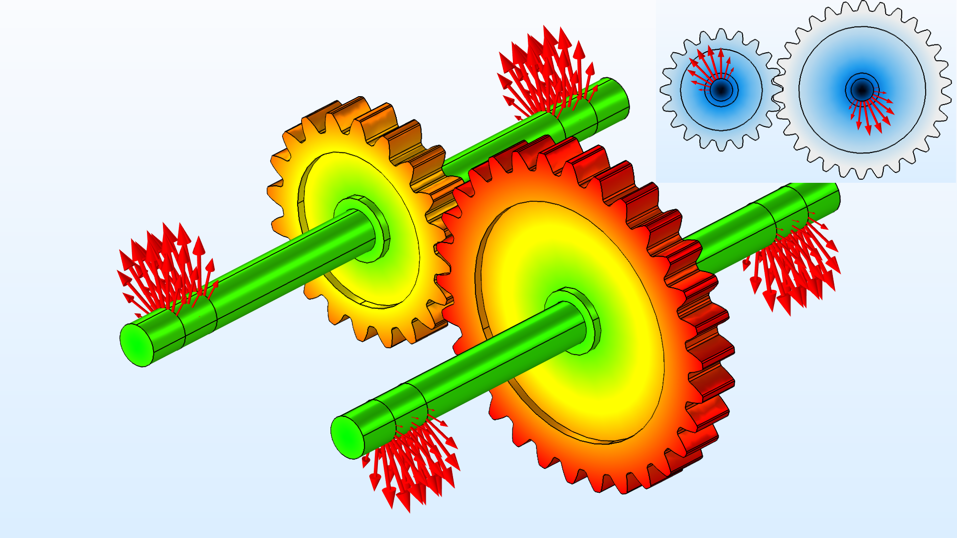
Displacement of rotors and roller forces at all bearings in a geared rotor assembly. Upper-right: front view.