Composite Materials Module Updates
For users of the Composite Materials Module, COMSOL Multiphysics® version 5.6 includes modeling of poroelastic layered shells, a new ply-based modeling approach for complex laminates, and support for damage and nonlinear materials in layered shells. Learn about these and other Composite Materials Module updates below.
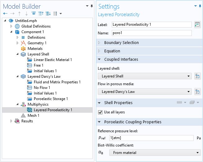
Poroelasticity, Layered Shell Multiphysics Interface
The new Poroelasticity, Layered Shell multiphysics interface enables modeling of multilayered domains (paperboards, composites, etc.) having different material properties per layer. The interface adds the Layered Shell and the new Layered Darcy’s Law interfaces, together with a new Layered Poroelasticity multiphysics node.
The new Layered Darcy’s Law interface, which is used in the above multiphysics interface, simulates the fluid flow through interstices in layered porous media, such as paperboards, composites, or plywood. You can model low-velocity flows and porous media flow where the permeability and porosity are very small, and for which the pressure gradient is the major driving force. Note that to access this functionality, you will need both the Porous Media Flow and Composite Materials modules.
Ply-Based Modeling Approach
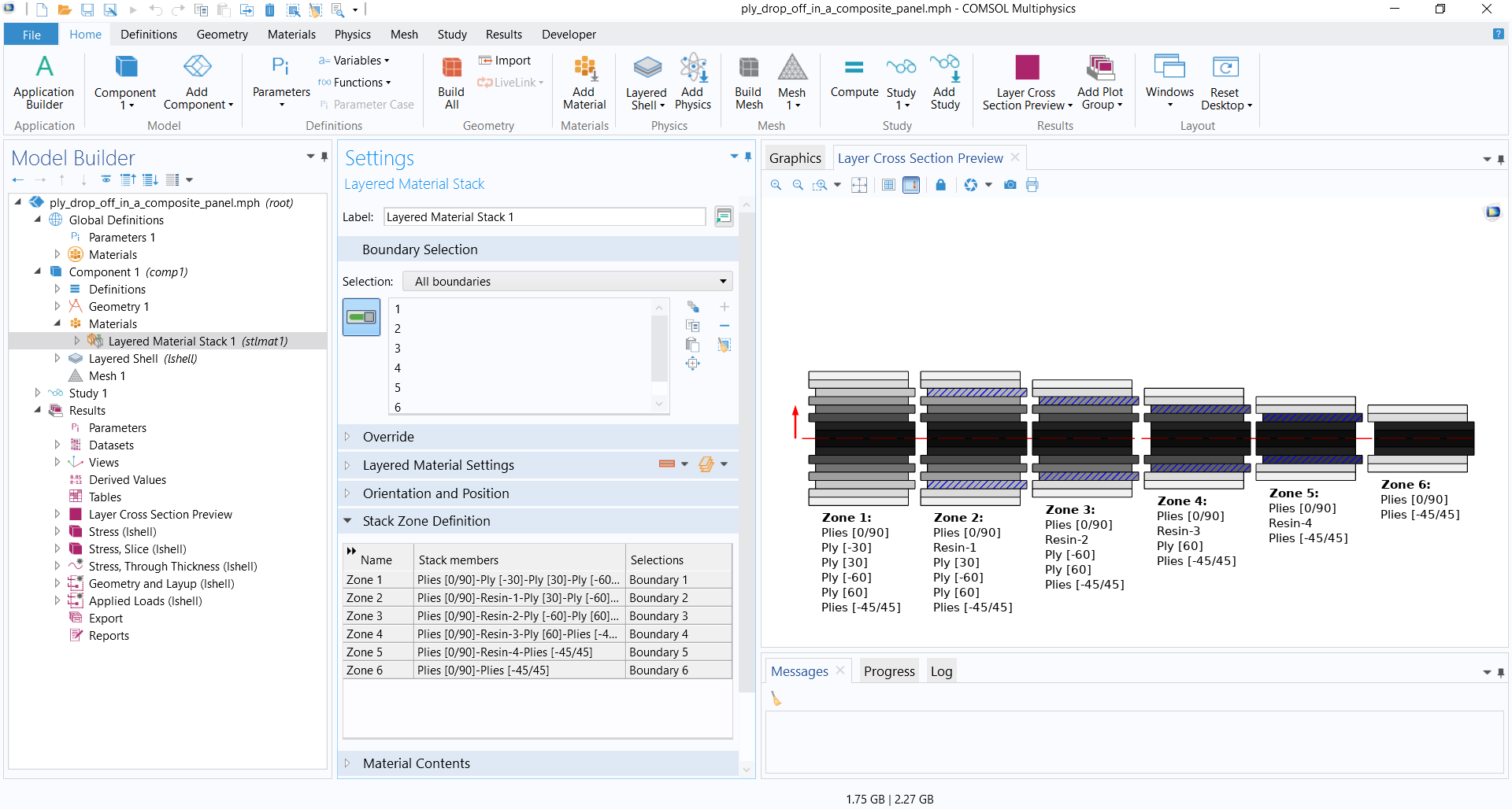
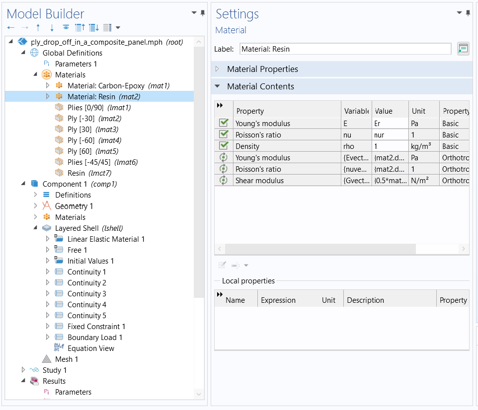
Support for a ply-based modeling approach has been added in order to define complex layups in a much easier manner compared to the existing zone-based modeling approach. This is available using the Selection input on the Layered Material Link, Layered Material, or Single Layer Material subnodes under the Layered Material Stack node. When the subnodes (or plies) are assigned different selections, the Layered Material Stack node automatically creates zones and the information about each zone is displayed in the Stack Zone Definition table. Each zone is treated as a different layered material and can be used accordingly in physics and postprocessing. You can see this new feature in the following models:
- Ply Drop-Off in a Composite Panel (new model)
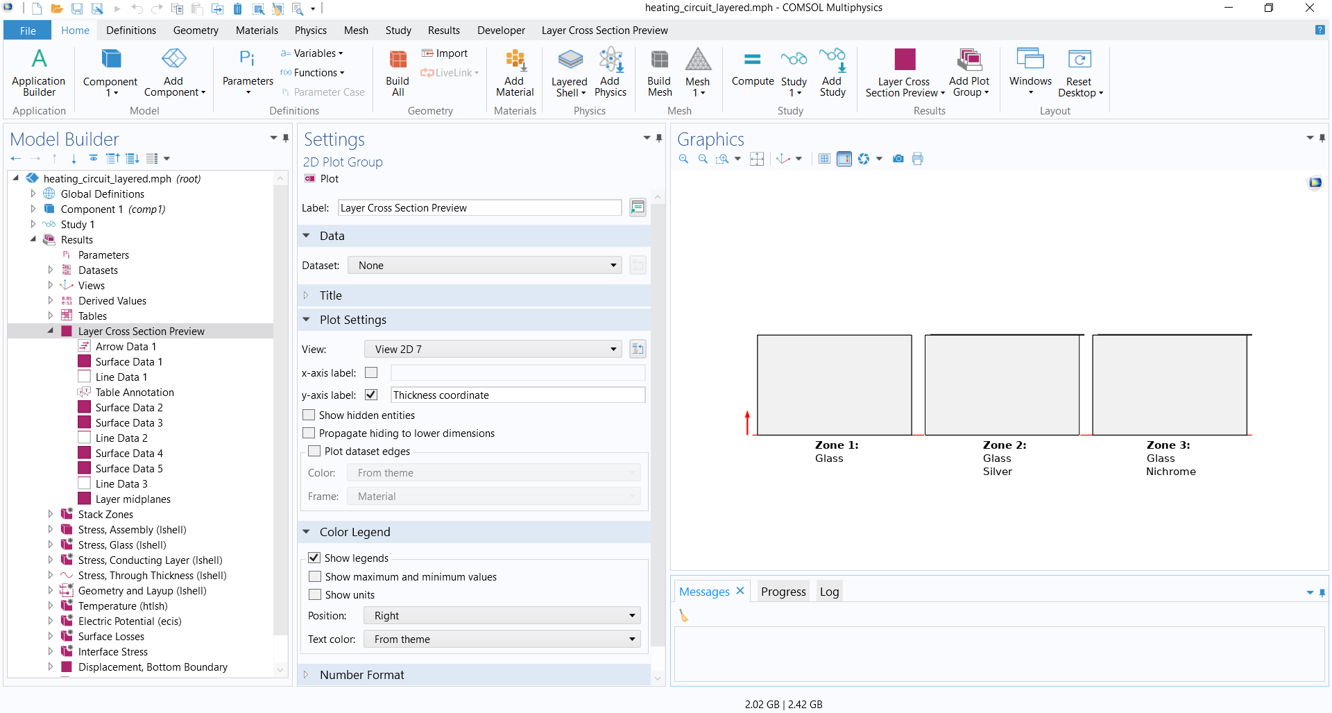
- Heating Circuit: Layered Shell Version (new model)
Performance Improvement in FSDT Shells
The performance of First-Order Shear Deformation Theory (FSDT) shells, implemented for the Layered Linear Elastic Material option in the Shell interface, is improved significantly for simpler use cases. A new NMQ formulation has been added to integrate the energy expressions only on the modeled surface instead of integrating in the full virtual solid domain. The new formulation is quite useful in composite sizing problems and used automatically for most cases.
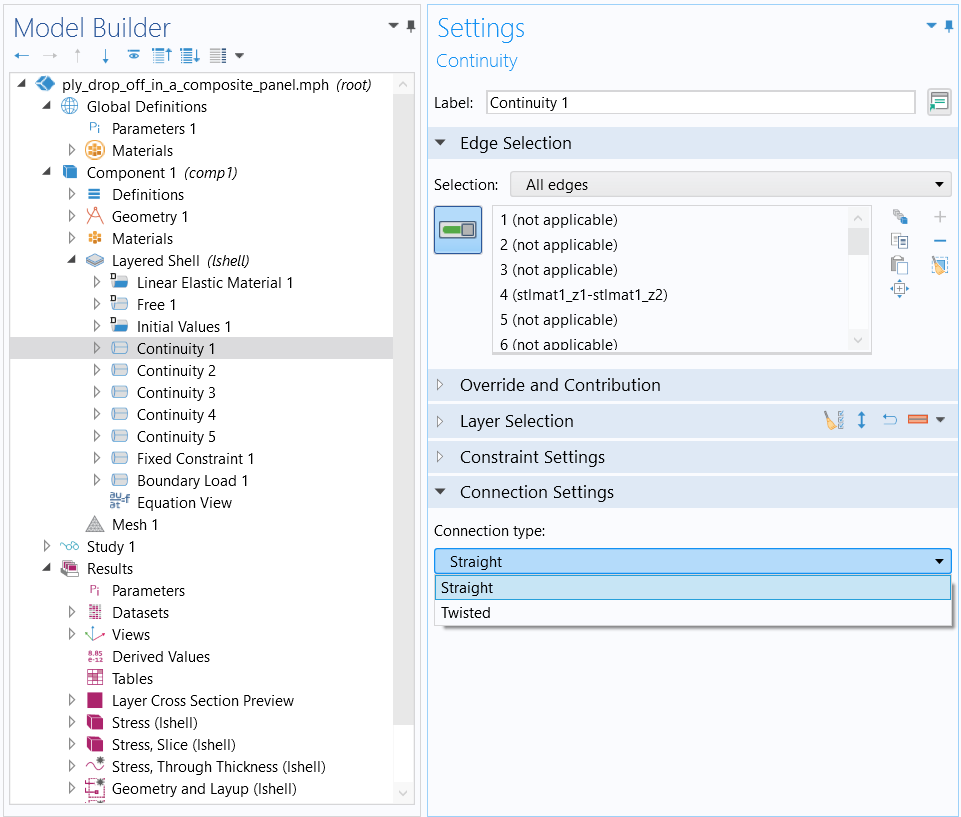
Connection Type in Layered Material Continuity
A new option of Connection type has been added in the Continuity node of the Layered Shell interface. The new option is available when Advanced Physics Options is enabled. The two choices in the connection type input are Straight and Twisted. The twisted connection type connects the two layered materials meeting side by side in reversed order by connecting the top of one layered material to the bottom of the other layered material. The twisted connection is particularly useful when adjacent boundaries have different orientations.
Changed Default Solid Model in the Layered Shell Interface
The default Solid Model of the Linear Elastic Material in the Layered Shell interface has switched from Isotropic to Orthotropic. The orthotropic solid model is a more natural choice for composite materials. For cases where an isotropic material is used, its equivalent orthotropic properties are automatically computed.
Layered Material Preview Plot Enhancement
Support for including layered material preview plots in an application has been added. This is available as a new preview plot option under the Results node. Two new buttons, Create Layer Cross Section Plot and Create Layer Stack Plot, are added on all of the layered material nodes to create such plots. In addition to being able to use it in an application, the new functionality can also be used for storing various preview plots in a model.
Mixed Formulation in Layered Linear Elastic Material
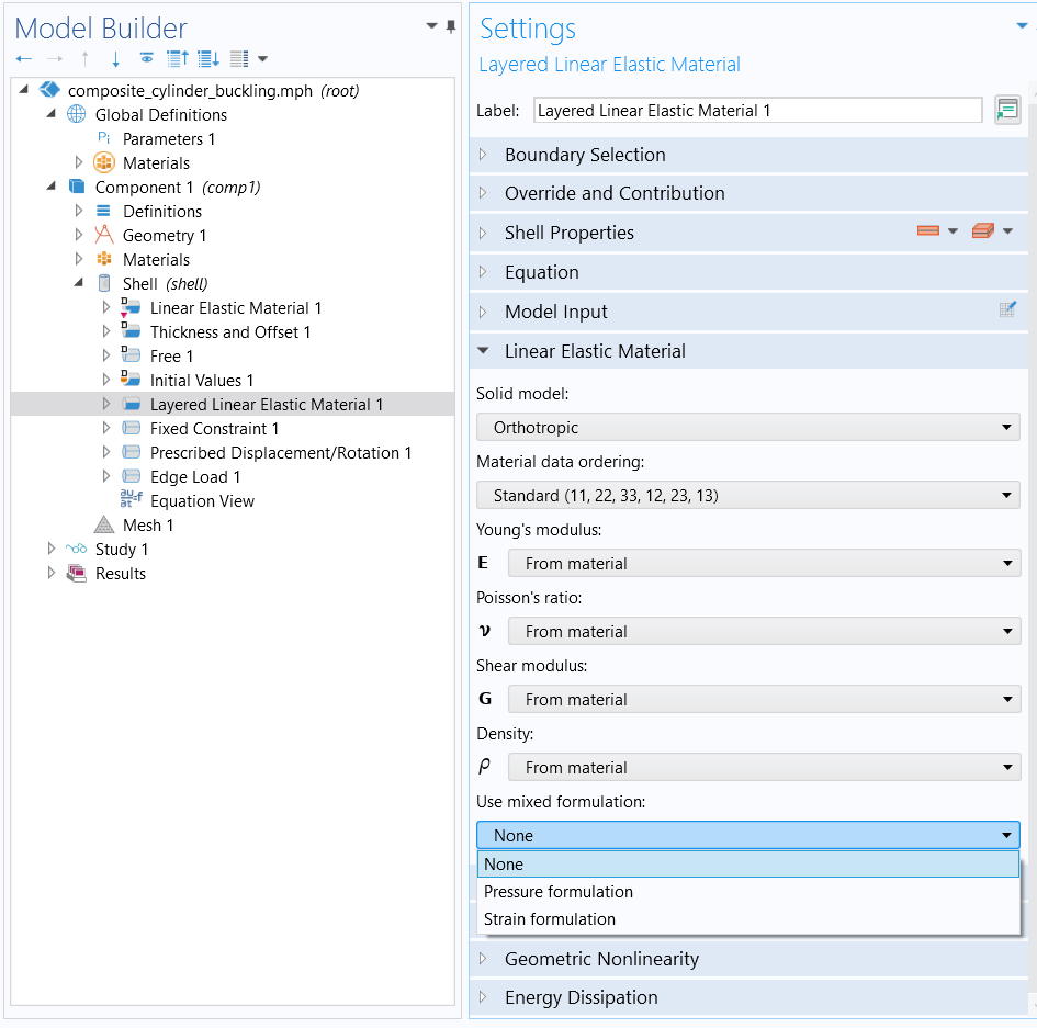
For the Layered Linear Elastic Material node, in the Shell interface, support for using a mixed formulation has been added. The mixed formulation supports both Pressure formulation and Strain formulation. It can be used to improve accuracy for materials with low compressibility.
The mixed formulation in a single-layer shell is available with the Structural Mechanics Module. If the Composite Materials Module is available, the mixed formulation can also be used in multilayered shells.
Viscous Damping in Layered Linear Elastic Material
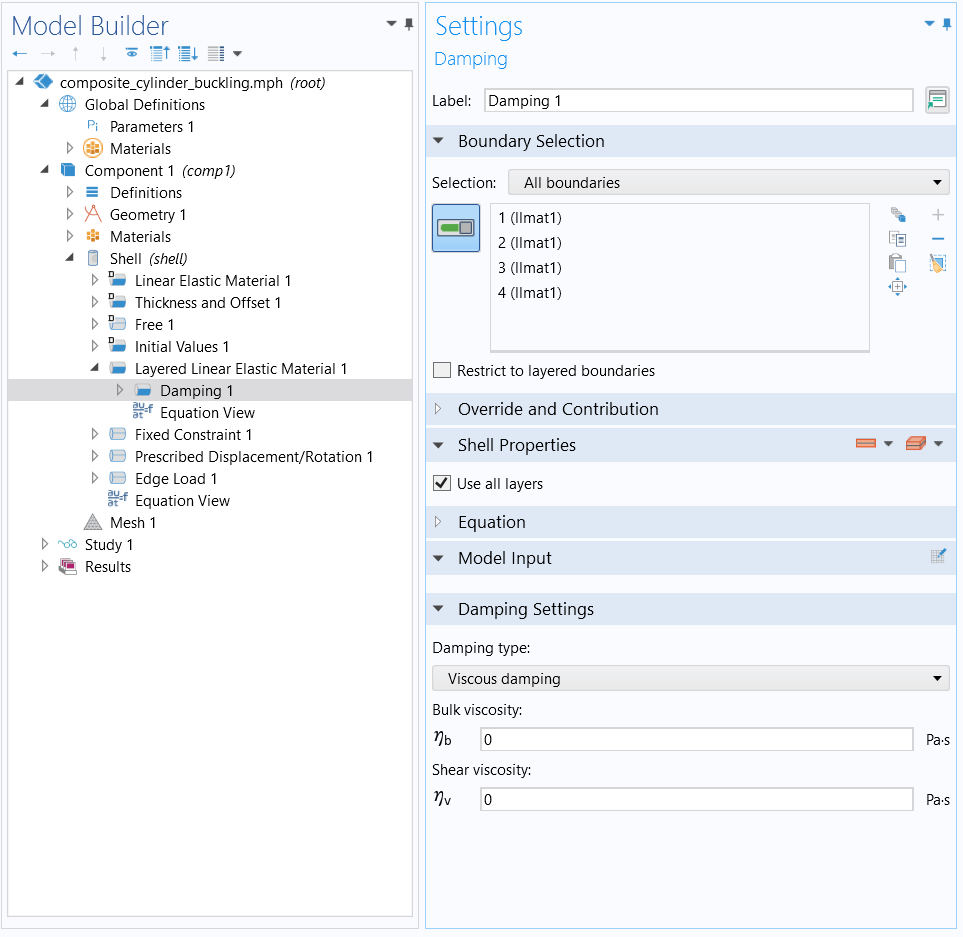
Viscous damping can now be added to the Damping subnode under Layered Linear Elastic Material in the Shell interface.
The viscous damping for a single-layer shell is available with the Structural Mechanics Module. If the Composite Materials Module is available, the viscous damping can also be used in multilayered shells, and the individual layers can have different damping values.
Damage in Layered Shells
All the Damage models available in the Solid Mechanics interface are now available for the Layered Linear Elastic Material node in the Shell interface, as well as for the Linear Elastic Material node in the Layered Shell interface. This feature requires the Nonlinear Structural Materials Module.
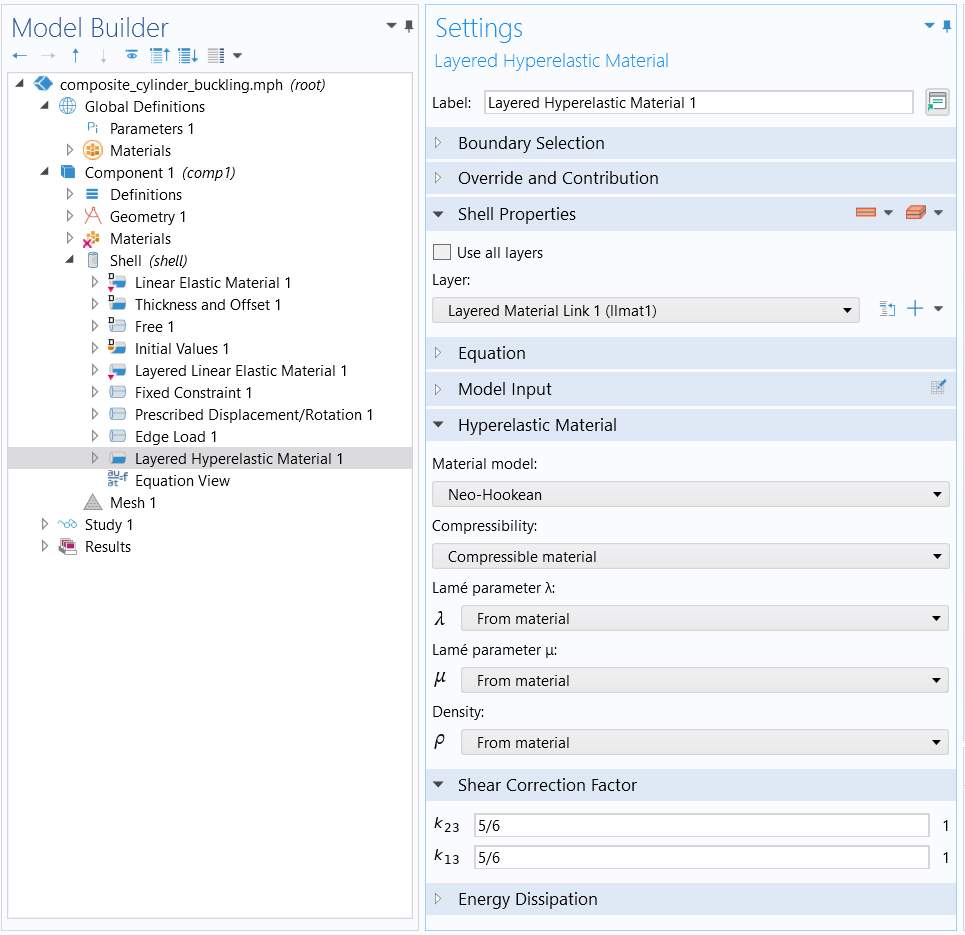
Layered Hyperelastic Material in Shell Interface
All of the Hyperelastic Material models available in the Solid Mechanics interface are now available for the Layered Hyperelastic Material node in the Shell interface. This feature requires the Nonlinear Structural Materials Module. If the Composite Materials Module is available, the material models can also be used in multilayered shells, and the individual layers can have different material models.
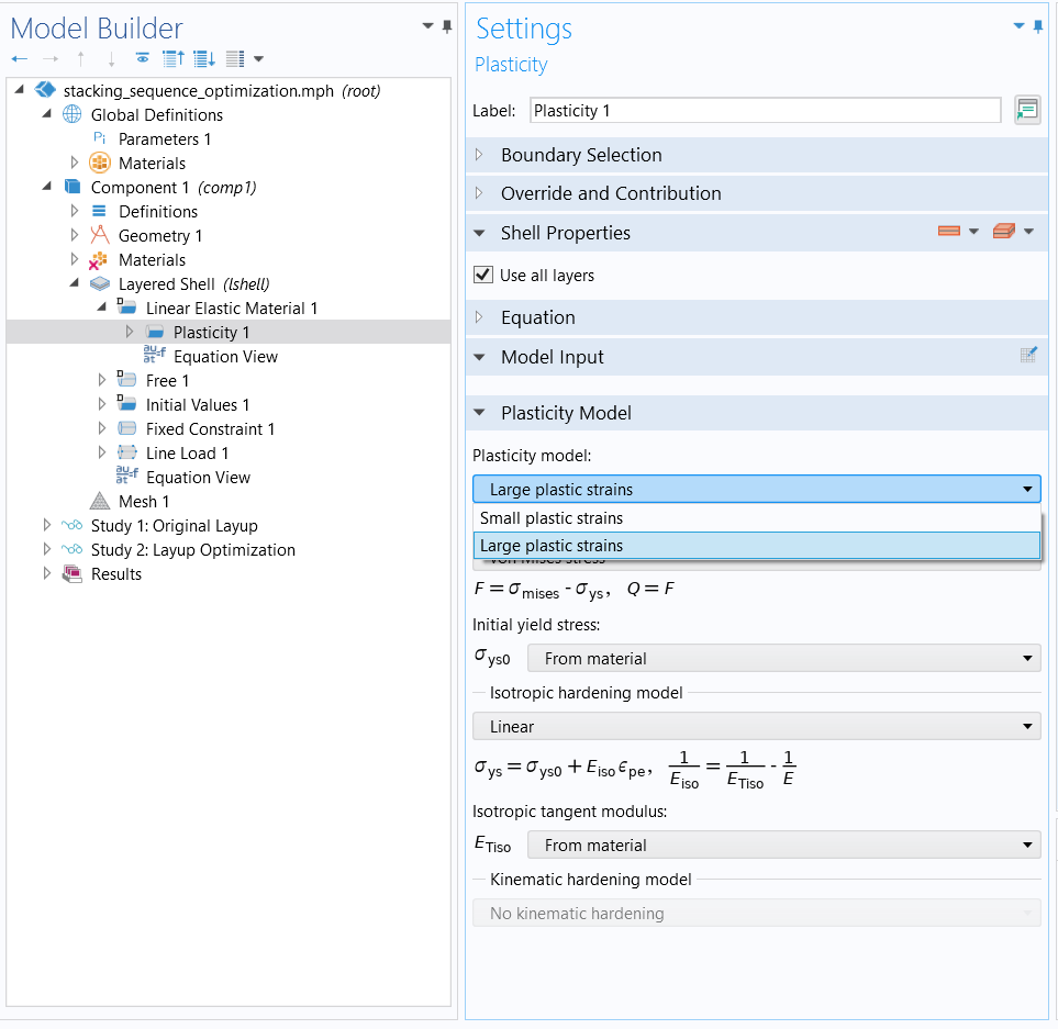
Large-Strain Plasticity in Layered Shell Interface
The Linear Elastic Material in the Layered Shell interface now includes the possibility to model Large-Strain Plasticity. The same set of yield functions and isotropic hardening models as in the Solid Mechanics interface are available.
It is now possible to add Plasticity to the Hyperelastic Material node in the Layered Shell interface. The new subnode uses the Large-Strain Plasticity formulation. The same set of yield functions and isotropic hardening models are available as in the Hyperelastic Material node for the Solid Mechanics interface. This feature requires the Nonlinear Structural Materials Module.
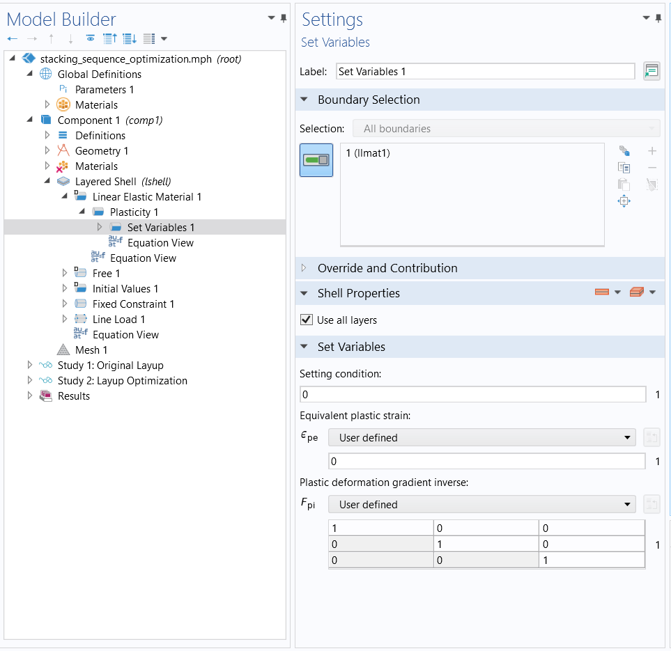
Set Variables Node Under Plasticity
A new subnode called Set Variables has been added to the Plasticity node, which is available as a subnode to the Linear Elastic Material node in the Layered Shell interface and Layered Linear Elastic Material in the Shell and Membrane interfaces. The purpose of this node is to reset plastic DOFs to model cases like stress relieving and annealing. This feature requires the Nonlinear Structural Materials Module.
Miscellaneous Improvements
- In the External Stress subnode of the Linear Elastic Material node in the Layered Shell interface, a new option of Pore Pressure has been added.
- Improvements in handling variable thickness layers in the Layered Shell, Shell, and Membrane interfaces.
- Default continuity is imposed on the common edges of Rigid Domain and Layered Linear Elastic Material (or similar) in the Shell interface.
- New operator xdintopallint has been added for integrating a quantity in all interfaces of all the layered materials.
- The Delamination node can now be added on only a few interfaces with partial base surface selection.
- The default plots for the Layered Linear Elastic Material in the Shell and Membrane interfaces have been improved.
New Tutorial Models
COMSOL Multiphysics® version 5.6 brings several new tutorial models to the Composite Materials Module.
Ply Drop-Off in a Composite Panel
Application Library Title:
ply_drop_off_in_a_composite_panel
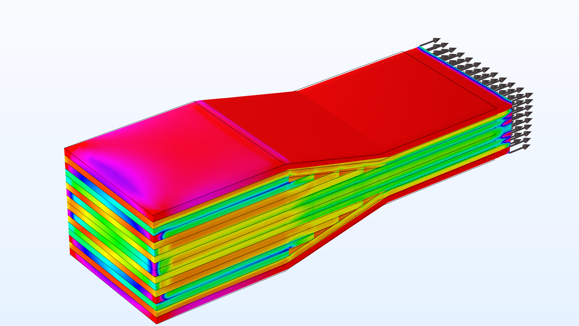
Stacking Sequence Optimization
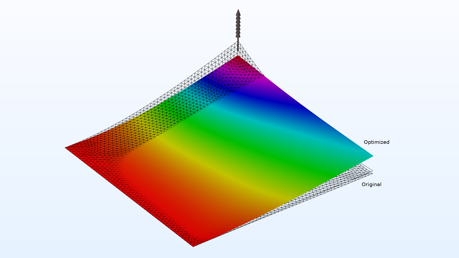
Application Library Title:
stacking_sequence_optimization
Heating Circuit: Layered Shell Version
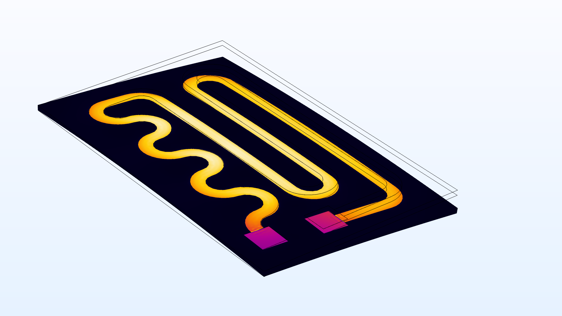
Application Library Title:
heating_circuit_layered