Meshing Updates
COMSOL Multiphysics® version 6.0 brings significant meshing improvements that make it easier and more efficient to set up simulations on imported mesh data, such as support for uniting meshes, boundary layer meshing, and curved elements. Browse all of the mesh updates below.
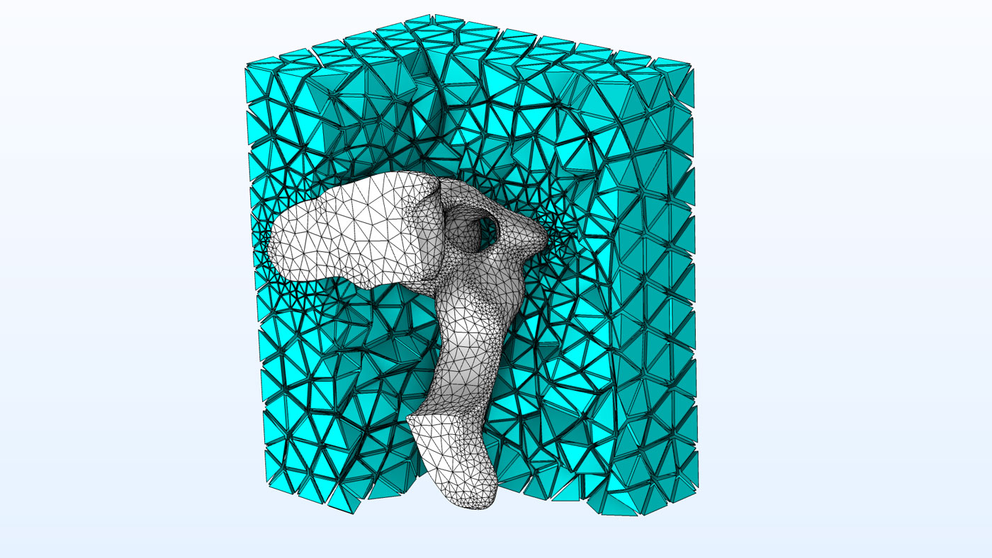
Uniting Imported Meshes
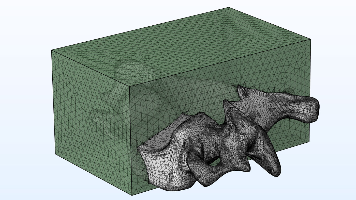
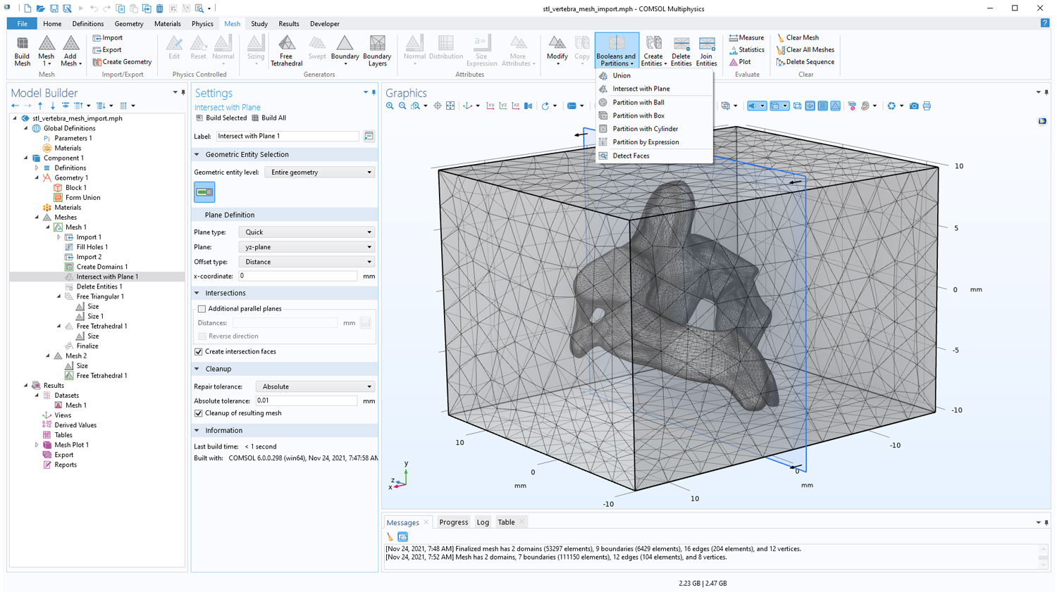
The new Union operation can be used to unite intersecting meshes. Use this operation to combine meshes, such as two imported meshes, or to combine an imported mesh with a geometry drawn in either COMSOL Multiphysics® or an external CAD software. As shown in the image below, an imported STL mesh is united with the mesh of a block, where the block has been drawn in the geometry sequence, meshed, and then imported into the same meshing sequence as the STL mesh.
Boundary Layer Meshing for Imported Meshes
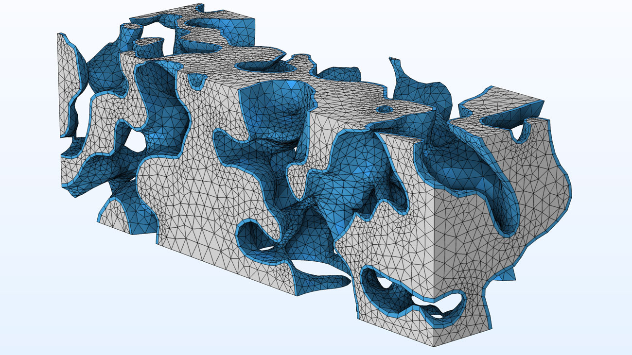
In COMSOL Multiphysics® version 6.0, it is straightforward to add boundary layer elements to all meshes, including imported meshes. To adapt an imported mesh to, for example, a fluid flow simulation, you can simply add a Boundary Layers operation to the sequence of mesh operations. This is shown in the Analyzing Porous Structures on the Microscopic Scale tutorial model.
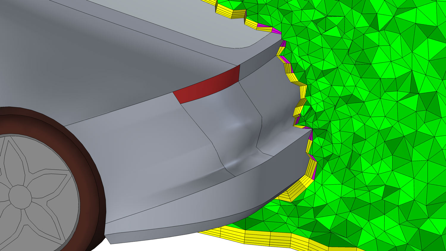
Curved Elements for Imported Meshes
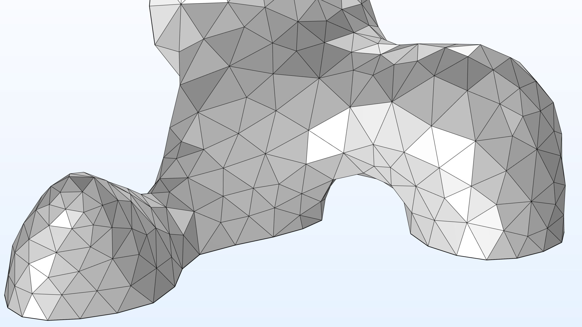
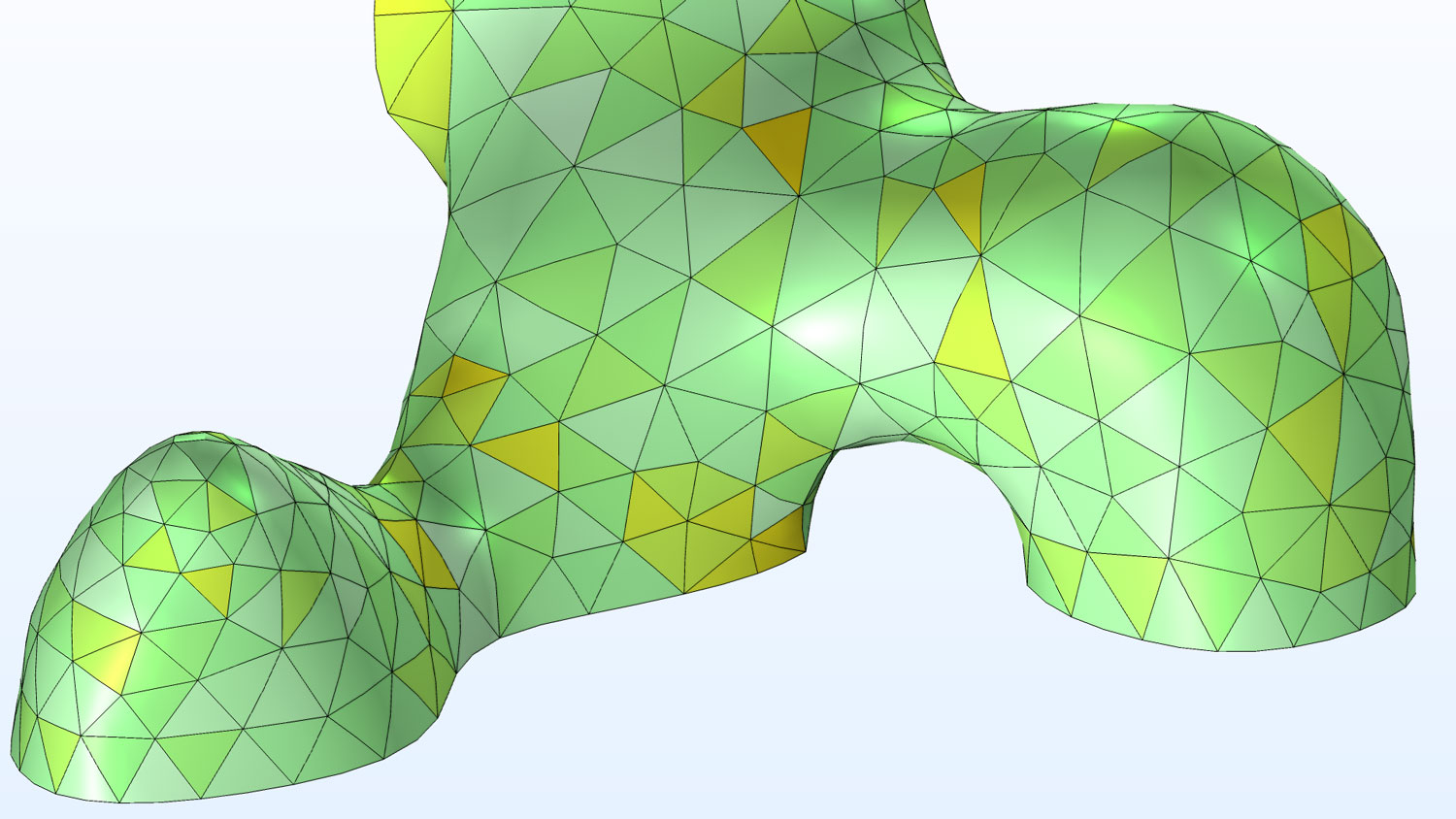
Curved elements can be reconstructed for meshes imported from file even in a case where they define linear elements. This includes STL, PLY, 3MF, and NASTRAN files. COMSOL Multiphysics® version 6.0 automatically estimates the shape of the faces and edges from the mesh structure to define curved elements specified by the discretization of the physics. There is no extra step needed and the curved elements are already set up and in use once you click the Compute button. To show the curved elements as displayed in the figure below, add a Mesh plot, and in the settings for the Mesh dataset, select a higher-order geometry shape function.
Transforming Imported Meshes
It is now possible to move, rotate, and scale an imported mesh using Transform attributes. To rotate the mesh around several axes, add several Transform attributes to the Import node. Previously, transformations were only supported in the geometry sequence.
Improved Usability for Mesh Editing
When you are meshing a geometry, you now have access to all operations for editing the mesh, including those that modify the number of geometric entities (the topology of the geometry), such as the new Union operation for meshes. These improvements make it easier to combine, in the same Component of your model, geometry created under the Geometry node with imported meshes, such as STL files.
Boundary Layer Meshing Improvements
COMSOL Multiphysics® version 6.0 includes improved support for boundary layer meshing on isolated boundaries. The boundary layer elements on interior and exterior wall boundaries now join smoothly at the intersections. This new way of joining boundary layer elements better resolves the physics that are close to such corners.
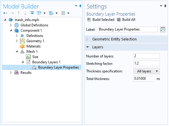
With COMSOL Multiphysics® version 6.0, it is also possible to specify the total thickness of the boundary layer elements. This gives more flexibility in the specification of the layers; you can enter the total thickness of all layers or the thickness of the first layer.
Mesh Plot Coloring Improvements
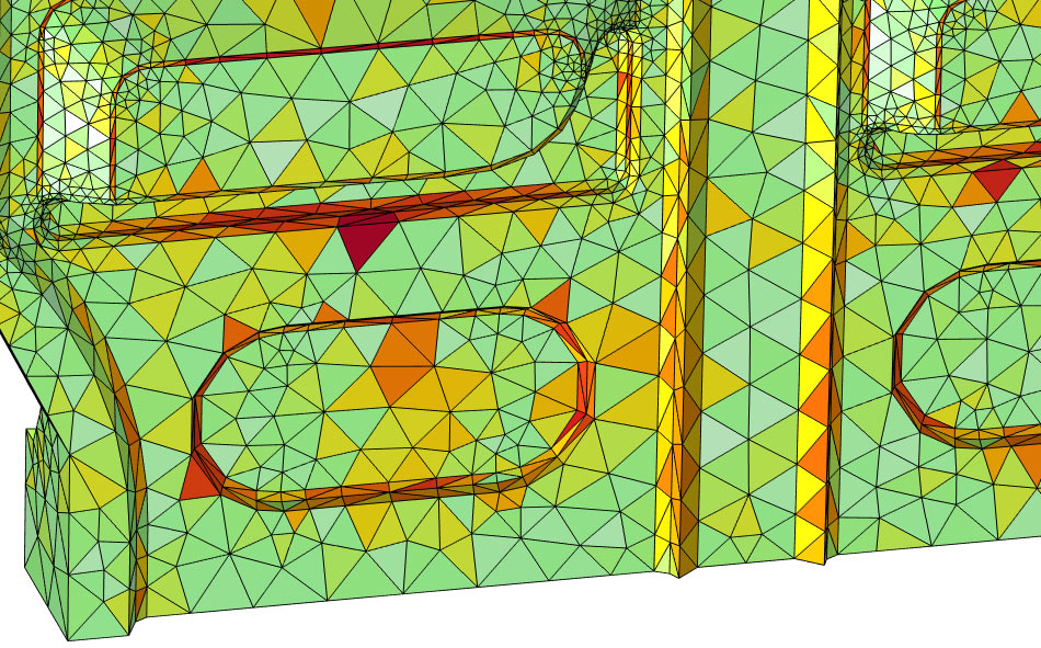
The new color table called Traffic Flow is designed to highlight elements of poor quality more clearly, and it is the default color table when you add a Mesh plot. The color table benefits people with color vision deficiency.
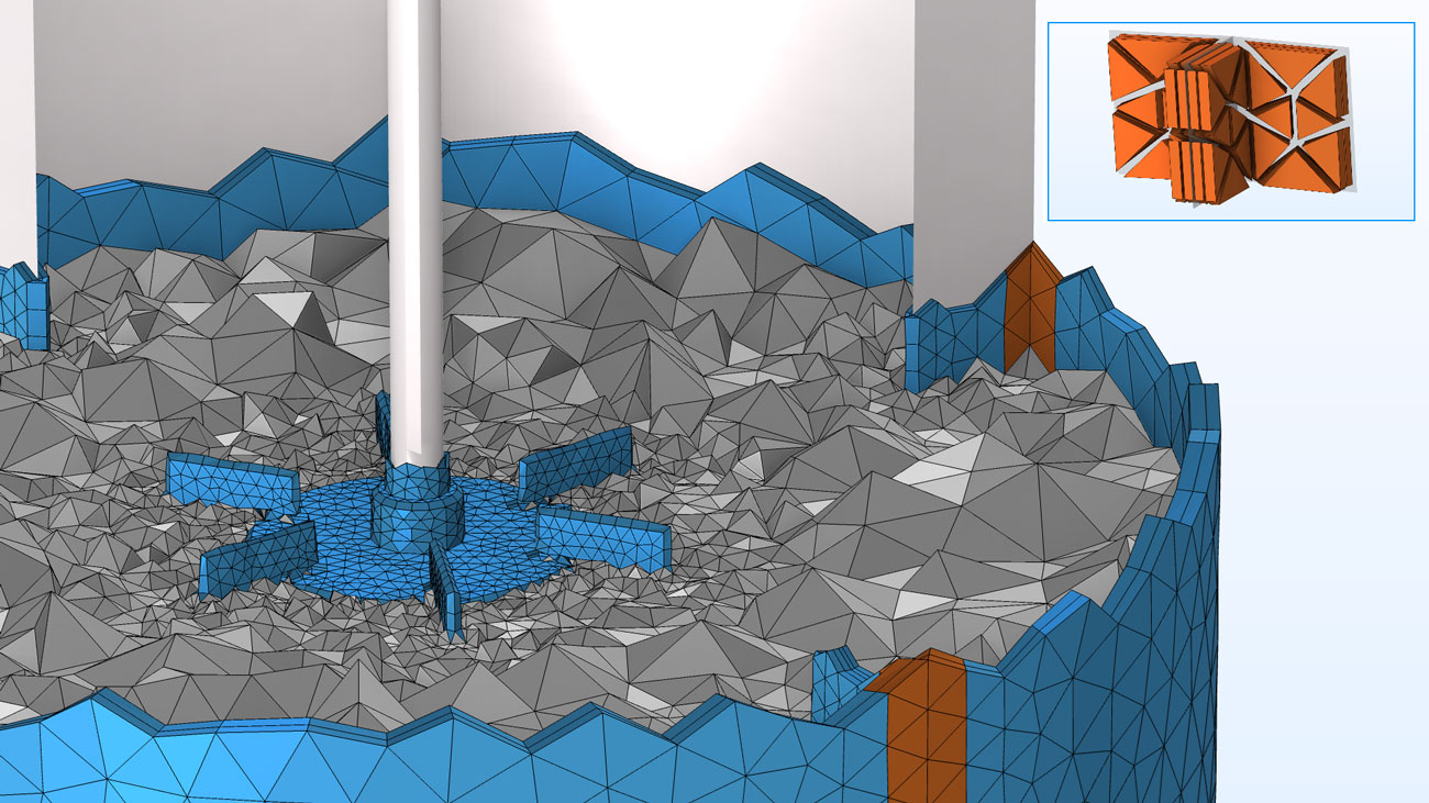
COMSOL Multiphysics® version 6.0 also comes with the possibility to color elements by their type in a mesh plot. You can use this new coloring option together with filtering to inspect the mesh elements inside domains in 3D, as illustrated in the figure.
Information About the Mesh Build
Some warnings that may appear when running mesh operations have been converted into Information nodes to better indicate the severity of the feedback. For all Information, Warning, and Error nodes that contain coordinates, you can now easily zoom and clip around the coordinates with dedicated buttons in the Settings window for these nodes. This makes it easier to closely inspect the region of the geometry featured in the feedback from the mesher.
An Information node with a coordinate specification locating an element of low quality. The new option to clip around the coordinates makes it easier to inspect the problematic region.
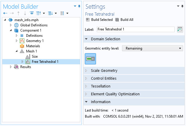
A new Information section is added to the Settings windows for all mesh operations. When the operation is built, this section displays the build time, build version, and other information.
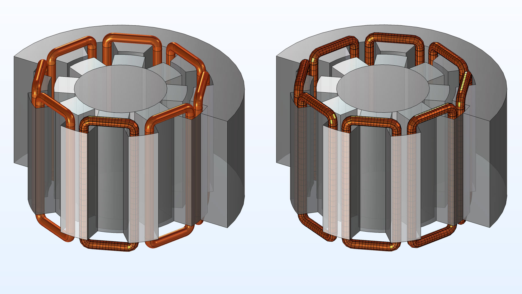
More Efficient Mesh Copying
In the case of several similar connected components of entities, it is now possible to use only one Copy operation to copy the mesh from one component to the other components. In the example shown below, each copper coil consists of four domains and defines a connected component. The improved mesh copy makes it straightforward to copy the mesh from one coil to all the other coils in the geometry.
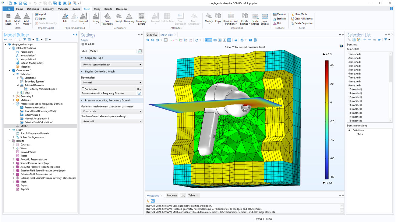
Physics-Controlled Meshing for Pressure Acoustics
Physics-controlled meshing is now supported for the Pressure Acoustics, Frequency Domain and Pressure Acoustics, Transient interfaces. This automatically gives suitable mesh size for the current wavelength, structured mesh in perfectly matched layers (PML), mesh copying for boundaries with applied periodic conditions, and boundary layer mesh for Exterior Field calculations.
Updated Tutorial Model
COMSOL Multiphysics® version 6.0 brings an updated meshing tutorial model.
Remeshing an Imported Mesh Without Generating a Geometry
Application Library Title:
stl_vertebra_import
Download from the Application Gallery