
In this blog entry, we introduce meshing considerations for linear static finite element problems. This is the first in a series of postings on meshing techniques that is meant to provide guidance on how to approach the meshing of your finite element model with confidence.
About Finite Element Meshing
The finite element mesh serves two purposes. It first subdivides the CAD geometry being modeled into smaller pieces, or elements, over which it is possible to write a set of equations describing the solution to the governing equation. The mesh is also used to represent the solution field to the physics being solved. There is error associated with both the discretization of the geometry as well as discretization of the solution, so let’s examine these separately.
Geometric Discretization
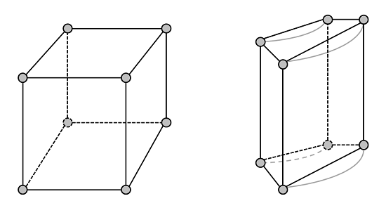
Consider two very simple geometries, a block and a cylindrical shell:

There are four different types of elements that can be used to mesh these geometries — tetrahedra (tets), hexahedra (bricks), triangular prismatics (prisms), and pyramid elements:

The grey circles represent the corners, or nodes, of the elements. Any combination of the above four elements can be used. (For 2D modeling, triangular and quadrilateral elements are available.) You can see by examination that both of these geometries could be meshed with as few as one brick element, two prisms, three pyramids, or five tets. As we learned in the previous blog post about solving linear static finite element problems, you will always arrive at a solution in one Newton-Raphson iteration. This is true for linear finite element problems regardless of the mesh. So let’s take a look at the simplest mesh we could put on these structures. Here’s a plot of a single brick element discretizing these geometries:
The mesh of the block is obviously a perfect representation of the true geometry, while the mesh of the cylindrical shell appears quite poor. In fact, it only appears that way when plotted. Elements are always plotted on the screen as having straight edges (this is done for graphics performance purposes) but COMSOL usually uses a second-order Lagrangian element to discretize the geometry (and the solution). So although the element edges always appear straight, they are internally represented as:
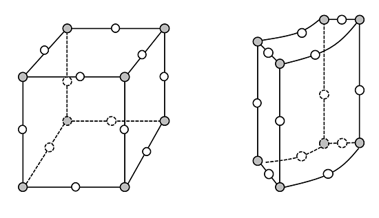
The white circles represent the midpoint nodes of these second-order element edges. That is, the lines defining the edges of the elements are represented by three points, and the edges approximated via a polynomial fit. There are also additional nodes at the center of each of these quadrilateral faces and in the center of the volume for these second-order Lagrangian hexahedral elements (omitted for clarity). Clearly, these elements do a better job of representing the curved boundaries of the elements. By default, COMSOL uses second-order elements for most physics, the two exceptions are problems involving chemical species transport and when solving for a fluid flow field. (Since those types of problems are convection dominated, the governing equations are better solved with first-order elements.) Higher order elements are also available, but the default second-order elements usually represent a good compromise between accuracy and computational requirements.
The figure below shows the geometric discretization error when meshing a 90° arc in terms of the number of first- and second-order elements:
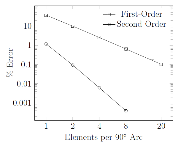
The conclusion that can be made from this is that at least two second-order elements, or at least eight first-order elements, are needed to reduce the geometric discretization error below 1%. In fact, two second-order elements introduce a geometric discretization error of less that 0.1%. Finer meshes will more accurately represent the geometry, but will take more computational resources. This gives us a couple of good practical guidelines:
- When using first-order elements, adjust the mesh such that there are at least eight elements per 90° arc
- When using second-order elements, use two elements per 90° arc
With these rules of thumb, we can now estimate the error we’ve introduced by meshing the geometry, and we can do so with some confidence before even having to solve the model. Now let’s turn our attention to how the mesh discretizes the solution.
Solution Discretization
The finite element mesh is also used to represent the solution field. The solution is computed at the node points, and a polynomial basis is used to interpolate this solution throughout the element to recover the total solution field. When solving linear finite elements problems, we are always able to compute a solution, no matter how coarse the mesh, but it may not be very accurate. To understand how mesh density affects solution accuracy, let’s look at a simple heat transfer problem on our previous geometries:
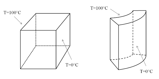
A temperature difference is applied to opposing faces of the block and the cylindrical shell. The thermal conductivity is constant, and all other surfaces are thermally insulated.
The solution for the case of the square block is that the temperature field varies linearly throughout the block. So for this model, a single, first-order, hexahedral element would actually be sufficient to compute the true solution. Of course, you will rarely be that lucky!
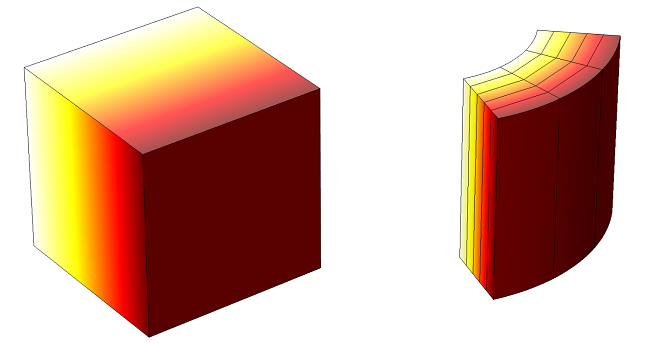
Therefore, let’s look at the slightly more challenging case. We’ve already seen that the cylindrical shell model will have geometric discretization error due to the curved edges, so we would start this model with at least two second-order (or eight first-order) elements along the curved edges. If you look closely at the above plot, you can see that the element edges on the boundaries are curved, while the interior elements have straight edges.
Along the axis of the cylinder, we can use a single element, since the temperature field will not vary in this direction. However, in the radial direction, from the inside to outside surface, we also need to have enough elements to discretize the solution. The analytic solution for this case goes as \ln(r) and can be compared against our finite element solution. Since the polynomial basis functions cannot perfectly describe the function, let’s plot the error in the finite element solution for both the linear and quadratic elements:
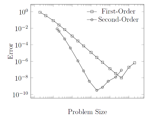
What you can see from this plot is that, as you increase the number of elements in the model, the error goes down. This is a fundamental property of the finite element method: the more elements, the more accurate your solution. Of course, there is also a cost associated with this. More computational resources, both time and hardware, are required to solve larger models. Now, you’ll notice that there are no units to the x-axis of this graph, and that is on purpose. The rate at which error decreases with respect to mesh refinement will be different for every model, and depends on many factors. The only important point is that it will always go down, monotonically, for well-posed problems.
You’ll also notice that, after a point, the error starts to go back up. This will happen once the individual mesh elements start to get very small, and we run into the limits of numerical precision. That is, the numbers in our model are smaller than can be accurately represented on a computer. This is an inherent problem with all computational methods, not just the finite element method; computers cannot represent all real numbers accurately. The point at which the error starts to go back up will be around \sqrt{2^{-52}} \approx 1.5 \times 10^{-8} and to be on the safe and practical side, we often say that the minimal achievable error is 10-6. Thus, if we integrate the scaled difference between the true and computed solution over the entire model:
We say that the error, \epsilon, can typically be made as small as 10-6 in the limits of mesh refinement. In practice, the inputs to our models will anyways usually have much greater uncertainty than this. Also keep in mind that in general we don’t know the true solution, we will instead have to compare the computed solutions between different sized meshes and observe what values the solution converges toward.
Adaptive Mesh Refinement
I would like to close this blog post by introducing a better way to refine the mesh. The plots above show that error decreases as all of the elements in the model are made smaller. However, ideally you would only make the elements smaller in regions where the error is high. COMSOL addresses this via Adaptive Mesh Refinement, which first solves on an initial mesh and iteratively inserts elements into regions where the error is estimated to be high, and then re-solves the model. This can be continued for as many iterations as desired. This functionality works with triangular elements in 2D and tetrahedrals in 3D. Let’s examine this problem in the context of a simple structural mechanics problem — a plate under uniaxial tension with a hole, as shown in the figure below. Using symmetry, only one quarter of the model needs to be solved.
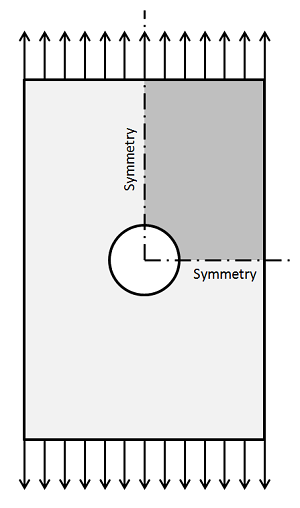
The computed displacement fields, and the resultant stresses, are quite uniform some distance away from the hole, but vary strongly nearby. The figure below shows an initial mesh, as well as the results of several adaptive mesh refinement iterations, along with the computed stress field.
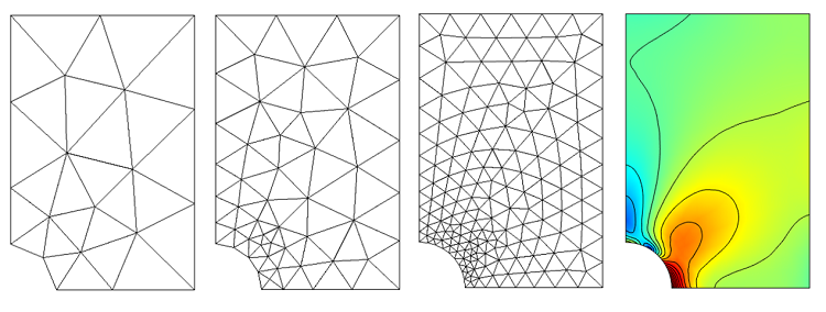
Note how COMSOL preferentially inserts smaller elements around the hole. This should not be a surprise, since we already know there will be higher stresses around the hole. In practice, it is recommended to use a combination of adaptive mesh refinement, engineering judgment, and experience to find an acceptable mesh.
Summary of Main Points
- You will always want to perform a mesh refinement study and compare results on different sized meshes
- Use your knowledge of geometric discretization error to choose as coarse a starting mesh as possible, and refine from there
- You can use adaptive mesh refinement, or your own engineering judgment, to refine the mesh


Comments (5)
Ivar Kjelberg
October 24, 2013Hei Walter
Thanks for detailed and clear explanations, looking forward for your next blog, will you talk more about:
– Dependent Variable and the estimation of their 1st, 2nd … derivatives (within 1 mesh element) and their relations to the mesh discretization order ?
– Rules of thumbs for minimum mesh densities for different physics: such as structural-modal, RF & optics waves, thermal – and diffusion – time models (and links to the diffusivity constants) …?
– Inverted elements, what can be considered as a warning, and what becomes critical
Another interesting topic is the post processing refinements done in COMSOL, when to use the wireframe, what can we learn by increasing, or turning off the mesh refinement …
These items often explains “surprising” (but explanable) negative absolute temperatures (in Kelvin) for HT time simulations, or the often encountered “negative concentrations” error messages
Sincerely
Ivar
Evgeni Sergeev
September 21, 2016I think it’s a little misleading to be saying “The error can typically be made as small as 10^-6 in the limits of mesh refinement” when we’re dealing with 64-bit floating-point (i.e. double) numbers, as Comsol is. In the plot above, as “Problem Size” increases, the error will keep growing beyond 10^-6, in fact becoming arbitrarily large, and that’s because the condition number of the matrix, that is the basis of the FEM solution, grows with mesh refinement at least linearly (or faster, depending on the problem). This comes up in practical simulations all the time, not just with very large DOF counts, because things like impedance mismatch can drive the condition number very high already with just a handful of elements.
So it’s important for users to be aware of this rapidly growing accumulated round-off error as they refine meshes. Especially with very large models.
Typically, the LinErr indicator reported by the Comsol’s solver does a good job of capturing this phenomenon, but often enough in my experience it underestimates it, sometimes by a few orders of magnitude. (Which must be because it’s based on a heuristic, as referenced in Comsol’s documentation.)
Walter Frei
September 21, 2016Hello Evgeni,
I do not think that the blog says that “The error can typically be made as small as 10^-6 in the limits of mesh refinement”.
It does, however, say that “…to be on the safe and practical side, we often say that the minimal achievable error is 10^-6” which is a much different statement than the former.
You are correct in that users should be aware of accumulating round-off errors as you refine the mesh, that is, after all the entire point of the plot of error vs. problem size.
In practice, however, the inflection point (the point where the error starts to rise due to round-off error) requires an EXCEPTIONALLY refined mesh, far beyond what is ever practically useful (since you will usually run out of memory before getting to this point!) In any case, by taking a systematic approach to your mesh refinement, as you should anyways always do, you will be able to clearly observe this point.
Best Regards,
Dominik Allgaier
June 6, 2018Hello Walter,
thx a lot for this very helpful and plain blog post.
I have a question.
When you have a look on the last picture (Mesh refinement iterations).
The left mesh has an geometrical error > 0,1 % referred to the (quarter) circle using second order elements.
But when I simulate the left mesh and the right mesh and compare the results, the difference in stress and displacement is < 10 %, also when using prism layers for the coarse mesh.
Do you have an explanation for this deviation?
Intuitively I´d choose the right, finer mesh to expect more accurate results. But unfortunately you can´t always resolve more complex geometries that fine …
Best regards
Dominik
Walter Frei
August 7, 2018Hello Dominik,
It would be correct to say that one often needs a quite fine mesh to achieve accurate stress results, yes. If one is constrained by computational resources (you don’t have enough RAM in your computer) consider using a submodeling (also called breakout modeling) strategy, as described here:
https://www.comsol.com/blogs/submodeling-how-analyze-local-effects-large-models-2/
https://www.comsol.com/model/submodeling-analysis-of-a-shaft-20359