Fluid Dynamics Modeling of an Industrial Wet Chemical Process Bath for the Si-Solar Cell Production
Silicon solar cells are produced in a series of different process steps in which wet-chemical etching and rinsing steps have a considerable influence on the quality of the wafers. Etching baths are used for surface structuring or intended etch back. Examples therefore are texturing, cleaning and conditioning [1,2], or etch back of the front emitter to improve electrical properties of the solar cell [3]. In order to increase the throughput in the industrial production of solar cells, wafers are processed in parallel batch processes in which a carrier, consisting of 100 Wafers, is dipped in a process basin. In the basin, the process solution is circulated by a pump, which pumps the solution into a supply pipe, through a perforated plate, along the carrier and over an overflow collar back to the pump. The requirements for optimal flow conditions over each individual wafer surface are very high, since different etching rates can result from an uneven flow [3]. By the use of computer-controlled flow simulations, the flow in an existing basin from the supply pipe to the overflow collar is simulated, with the aim of gaining a deeper understanding of the processes in the basin and optimizing the geometry for the future. In addition, the knowledge of the obtained flow conditions will be used to investigate flow-induced etching patterns. Since the basin contains several disturbances with partial high scale differences, the basin was divided into smaller models.
First, a three-dimensional model according to the supply pipe and basin was created. For all studies the COMSOL Multiphysics® CFD Module was used. To keep the model simple, the simulations were carried out, using water instead of the chemical mixture as initial material. Since it can be considered that a homogeneous outflow from the supply pipe can ensure a homogeneous flow in the basin, the outflow out of the supply pipe was obtained.
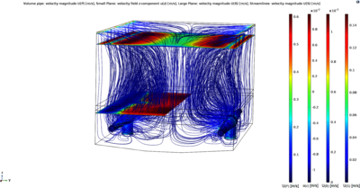
Our second simulation focused on the flow conditions in the basin (Figure 1). In order to save computational time, the results at the outputs of the already simulated supply pipe were used as input parameters for the second study, the flow into the basin. Since the fluid flows from a small flow area into a large flow area (scale 1:80), a simple turbulence model, the algebraic yPlus model, was used. The result of the second study was validated, using an acoustic digital flow meter for highly accurate point velocity measurement. As a result, the main flow could be determined with a deviation of 5 mm/s.
The next step is to simulate the flow through the perforated plate. Due to large scale differences, this flow is examined in a smaller model, consisting of just one hole.
References 1. E. Vazsonyi, K. de Clercq, R. Einhaus, E. van Kerschaver, K. Said, J. Poortmans, J. Szlufcik, J. Nijs, Solar Energy Materials and Solar Cells 57 (1999) 2. H. Schröder, Journal of Micromechanics and Microengineering 9 (1999) 3. A. Moldovan, Ozonbasierte Reinigungs- und Konditionierungsverfahren für die Herstellung hocheffizienter Silizium Solarzellen (Fraunhofer Verlag, Stuttgart, 2016)
Download
- mohr_presentation.pdf - 2.5MB
- mohr_paper.pdf - 0.83MB
- mohr_abstract.pdf - 0.54MB