

If you are using a cell phone, GPS, Bluetooth, or WiFi, chances are that they all have BAW resonators working inside them. All wireless electronic equipment use RF filters to help narrow down the frequency range they should operate within. With thousands of devices working within closely-packed radio frequencies, it is becoming increasingly important to design filters that would be able to reduce interference from unwanted frequencies, boost the signal-to-noise ratio, and lower insertion loss. Doing so may lead to fewer dropped calls in cell phones and less frequent charging of handheld electronic devices. Let’s have a look at how you can model a piezoelectric BAW resonator using simulation software.

Frequency response characteristics of a typical band pass filter.
Setting the Scene for Improved Electronic Device Design
In order to incorporate all the desired qualities of our electronic equipment and design a high Q narrow band-pass filter, we need to think beyond using traditional RLC circuits. This is where Surface Acoustic Wave (SAW) and Bulk Acoustic Wave (BAW) resonators come into the picture. Whereas SAW filters seem to rule the market for low frequency (below 1.5 GHz) applications, BAW filters become more efficient at higher frequencies, from 2 GHz to 16 GHz. Although BAW resonators are primarily used for making RF filters and duplexers that are used in wireless electronic devices, they can also be used for a variety of sensors, including chemical gas sensors and biosensors for detecting cancer, to name a couple of applications.
What is a BAW Resonator?
A BAW resonator is an electromechanical device in which a standing acoustic wave is generated by an electrical signal in the bulk of a piezoelectric material. In the simplest configuration, a device will consist of a piezoelectric material (typically quartz, AlN, or ZnO) sandwiched between two metallic electrodes. The natural frequency of the material and the thickness are used as design parameters to obtain a desired operating frequency. More complex designs will employ a ladder or lattice topology for better control over operating frequencies.

Schematic representation of the operation of a BAW resonator.
There are two popular configurations for BAW resonators:
- Thin Film Bulk Acoustic Wave Resonator (TFBAR or FBAR)
- Solidly Mounted Resonator (SMR)

Schematic representation of different BAW designs. The thickness shown is not to scale.
FBAR’s are typically designed in one of these two configurations: edge-supported or composite (see the figure for FBAR, above). In an edge-supported structure, the substrate is completely etched away on the back side, whereas in a composite configuration another dielectric material is placed below the main structure to act as a supporting layer. In an SMR, additional layers are placed below the main structure to serve as Bragg reflectors and provide structural support. Bragg reflectors minimize the leakage of the acoustic wave from the bulk structure.
In order to design a BAW resonator, it is crucial to take into account the electromechanical coupling that arises due to both geometric effects and multiphysics interaction. A high-definition simulation of the resonator could possibly help us address the following questions:
- What thickness and material properties of the different layers would help me get the desired resonance frequency?
- How much stress will develop in different parts of the device? Will it be beyond the desired operating level?
- How will the material damping and anchor loss affect the bandwidth of the filter?
- How does the impedance and Q factor vary as a function of the frequencies that I expect the device to encounter?
This is where COMSOL Multiphysics and the MEMS Module are useful.
Modeling a BAW Resonator in COMSOL Multiphysics
The MEMS Module offers a predefined physics interface for modeling piezoelectric devices, such as the BAW resonator. This makes it quite easy to work with multilayered geometries that would include both piezoelectric and non-piezoelectric materials. These materials could be isotropic or anisotropic, and may exhibit both structural damping and dielectric losses.
In many BAW designs, there are also supporting structures that form the anchor for the device. The loss due to such structures (anchor loss) can also be effectively modeled with COMSOL using perfectly matched layers (or PMLs). Once you set up the simulation with the appropriate information on the material properties and physics, you could solve an eigenfrequency analysis to first identify the resonance modes around your desired target value, and then perform a detailed frequency response analysis over the desired range of operating frequencies. For more detailed information on how to model a BAW resonator, check out our tutorial model on Thin Film BAW Composite Resonator.

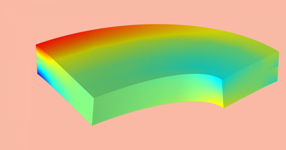
A snapshot of a simulation of a piezoelectric BAW resonator.
Additional Resources
- Our tutorial on modeling a Composite Piezoelectric Transducer is a good starting point for those of you interested in modeling SAW and BAW devices
- The Thickness Shear Mode Quartz Oscillator model tutorial is great for learning how to tune the resonance of a piezoelectric oscillator using a shunt capacitor


Comments (0)