Previously on the blog, we detailed the standards employed to describe piezoelectric materials. There are two piezoelectric material standards supported in COMSOL Multiphysics: the IRE 1949 standard and the IEEE 1978 standard. Today, we will demonstrate how to set up the orientation of a crystal, specifically an AT cut quartz plate, within both standards.
Setting Up the Orientation of a Crystal in Two Standards
To set up the orientation of a crystal within COMSOL Multiphysics, it is necessary to specify the orientation of the crystallographic axes with respect to the global coordinate axes used to define the geometry. This is different than the manner in which the standards define the crystal orientation. Thus, some care is needed when defining the orientation of the geometry. For example, the orientation of the crystal axes will change if the orientation of the plate is changed. Here, we will show how to set up an AT cut quartz plate in different orientations in the physical geometry.
In a previous blog post, we discussed in detail the system that is used in both the IEEE 1978 standard and the IRE 1949 standard. Due to differences in the orientation of the crystallographic axes specified by each standard, the definition of the AT cut differs between them. The table below shows both definitions of the AT cut:
| Standard | AT Cut Definition |
|---|---|
| IRE 1949 | (YXl) 35.25° |
| IEEE 1978 | (YXl) -35.25° |
The difference between the standards can be understood by recalling that the plate cut from the crystal has an orientation defined by the l–w–t axes set (l–w–t stands for length, width, and thickness). The first two letters given in parentheses in the cut definition — Y and X — define the crystal axes with which the l and t axes are originally aligned. A rotation of 35.25° is then performed about the l-axis. The sense of the rotation differs between the standards, since the material properties are defined with respect to different sets of axes within the standards. This is illustrated in the figure below, which shows that the rotation about the l-axis is in a positive sense for the 1978 standard, but a negative sense for the 1949 standard.
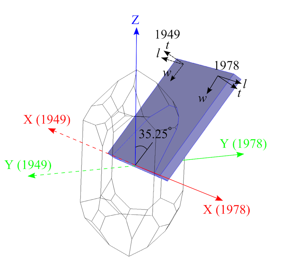
The AT cut of quartz (mauve cuboid) shown together with a right-handed quartz crystal. The axes sets adopted by the IRE 1949 standard and the IEEE 1978 standard are shown, as well as the orientations of the l–w–t axes set in the plate.
There is another subtle difference between the two standards. As the AT cut is defined in the two standards, the thickness and length directions are reversed between them (shown in the figure above). From the figure, it is clear that to obtain exactly the same plate orientation as the 1949 standard, the 1978 standard would require an additional rotation of 180° about the w-direction. In this case, the AT cut in the 1978 standard would be defined as: (YXlw) -35.25° 180°. We need to carefully account for these differences between the standards when setting up a model in COMSOL Multiphysics.
Global Coordinate System
One way to set up a model is to keep the global coordinate system aligned with the crystal axes and simply rotate the plate to correspond with the first figure. As we will see, this method is perfectly valid, although it results in a rather inconvenient specification of the geometry.
Instead, we will consider how to define the material orientation for an AT cut quartz disc. In this COMSOL Multiphysics model, the crystal orientation is determined by the coordinate system selection in the Piezoelectric Material settings window. The crystal orientation is specified via a user-defined axis system that is selected in the coordinate system combo box, depicted below. This example is based on a simplified version of the Thickness Shear Mode Quartz Oscillator tutorial, available in our Application Gallery.
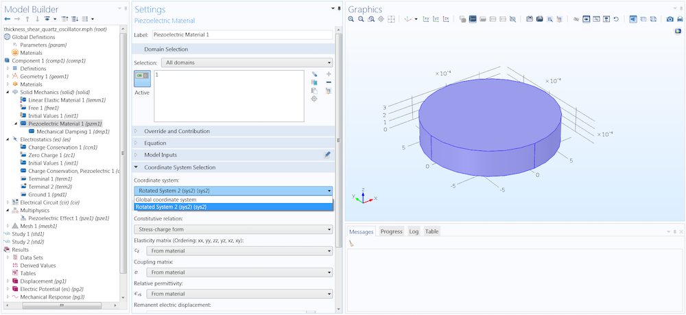
Changing the coordinate system for a piezoelectric material in COMSOL Multiphysics.
In the example above, the left-handed quartz defined in the 1978 standard is used for the material. If we wish to use the global coordinate system for the crystal orientation, then the quartz disc must be orientated in the manner shown in the first figure, with the axes set up for the 1978 standard. This can be achieved by rotating the cylinder about the x-axis.
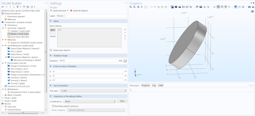
A rotation operation is applied to the quartz cylinder.
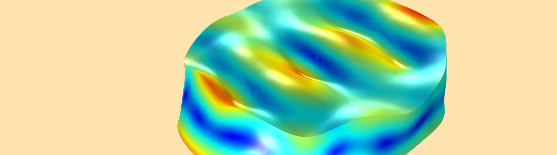
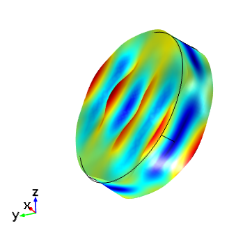
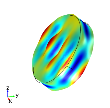
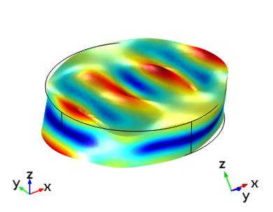
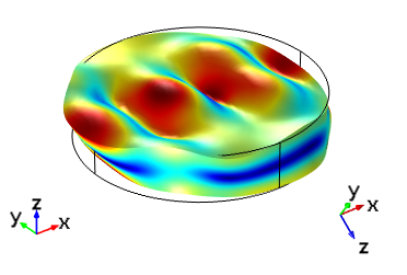
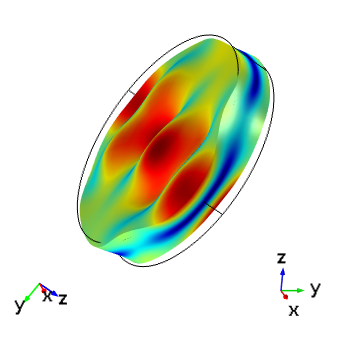
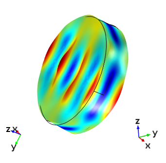
The images below show the response of the device when it is set up in the selected orientation. The crystal is vibrating in the thickness shear mode. To obtain this response, use Study 1 in the COMSOL Multiphysics Application Gallery file and solve for a single frequency of 5.095 MHz.
| IRE 1949 Standard | IEEE 1978 Standard |
|---|---|
|
|
Thickness shear mode of an AT cut crystal for the same plate set up with the IRE 1949 (left) and the IEEE 1978 (right) standards. The driving frequency is 5.095 MHz. In both cases, the global coordinate axes in COMSOL Multiphysics correspond to the crystal axes.
Setting up the model within the IRE 1949 standard is straightforward, as COMSOL Multiphysics includes the material properties for both left- and right-handed quartz in each standard. To use the alternative standard, simply add the Quartz LH (1949) material to the model and select the quartz disc. This will override the previously added material. Then, change the rotation angle of the disc to -54.75º to orientate the disc equivalent to the plate shown in the first figure. The figure above shows that when these steps are followed, the 1949 standard gives the same result as the 1978 standard. Although the two figures appear identical, the global axes have been rotated so that they correspond to the two axes sets in the first figure.
As this example shows, it is possible to use the global coordinate system for the crystal axes. However, for a cut such as the AT cut, this results in an unusual orientation of the plate within the geometry. In a real world application, one might have several piezoelectric elements in different orientations and then this approach could not be used for all of the crystals. Therefore, it is often more convenient to specify the crystal orientation by means of a rotated coordinate system.
Rotated Coordinate System
In the COMSOL Multiphysics environment, the most convenient way to specify a rotated coordinate system is through a set of Euler angles. The Euler angles required for a given crystal cut will vary for different orientations of the plate with respect to the model global coordinates. Now we will consider how to specify the Euler angles for two different plate orientations in both of the available standards.
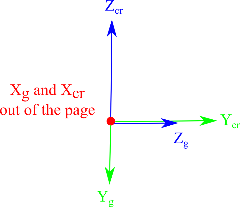
The best way to determine the Euler angles required within a given standard is to carefully draw a diagram that specifies the orientation of the l–w–t axes with respect to the crystal axes. Note that in some of the figures for the 1978 standard, l, w, and t are labeled as dimensions of the plate rather than as a set of right-handed axes. It is best to ensure that they are drawn as a set of right-handed axes to avoid potential confusion when determining the Euler angles for a plate in a COMSOL Multiphysics model. The Euler angles determine the orientation of the crystallographic axes (Xcr–Ycr–Zcr) with respect to the global coordinate system (Xg–Yg–Zg). Consequently, both the orientation of the plate with respect to the global system and the crystal cut determine the Euler angles.
As an example, we will consider the case where the global axes Xg–Yg–Zg align with the l–w–t axes (corresponding to the plate, with its thickness in the Zg direction). This is often the most convenient way to orientate the plate within a larger geometry. The figure below shows what happens when we take the first figure and rotate the plate such that the l, w, and t axes correspond to the global axes Xg–Yg–Zg within the two standards. For ease of comparison with the initial figure, the global axes are not in the same orientation for the two standards.
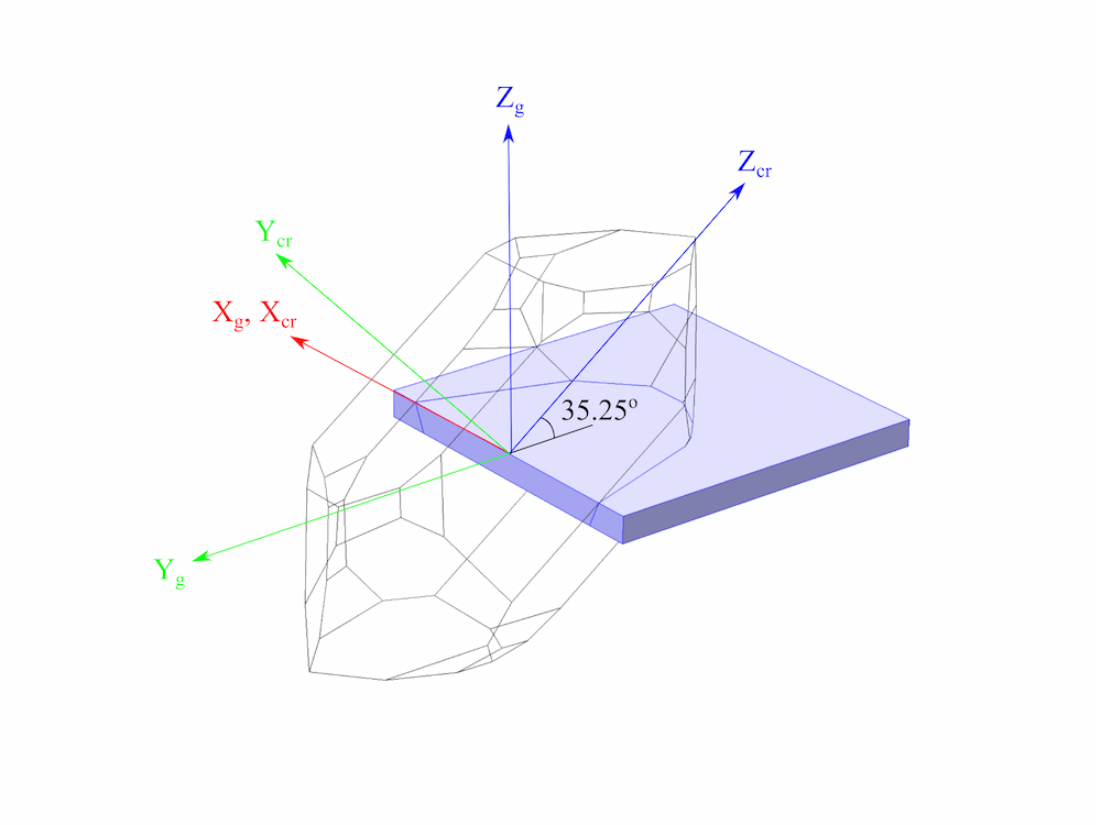
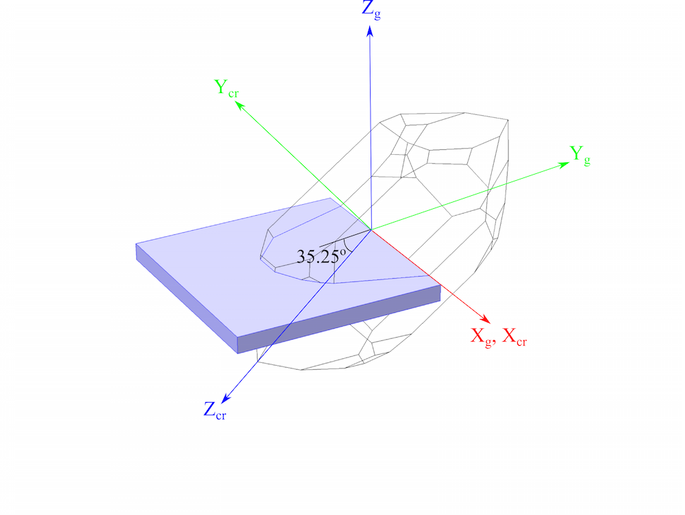
Rotated versions such that the l, w, and t axes correspond to the global axes Xg–Yg–Zg within the 1949 standard (left) and the 1978 standard (right). The Y and Z axes lie in a single plane.
The next figure shows the unrotated and rotated axes as seen from a side view of the first figure. This diagram represents an easier “paper and pencil” approach for determining the Euler angles.
| IRE 1949 Standard | IEEE 1978 Standard | |
|---|---|---|
| Orientation in unrotated axes |
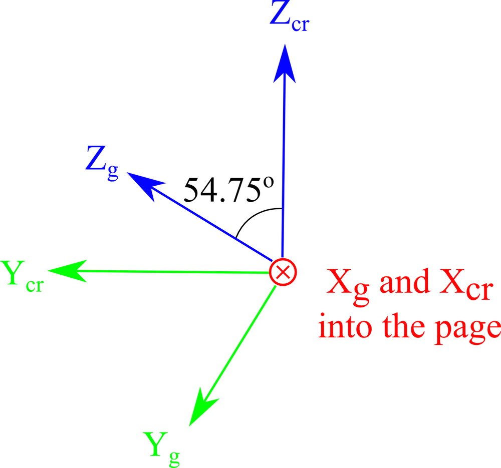
|
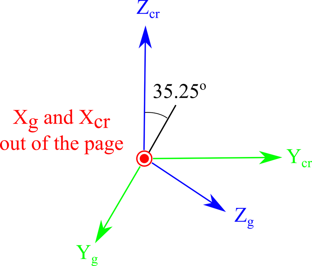
|
| Orientation in rotated axes |
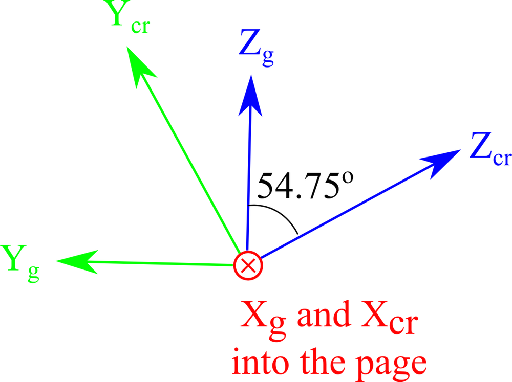
|
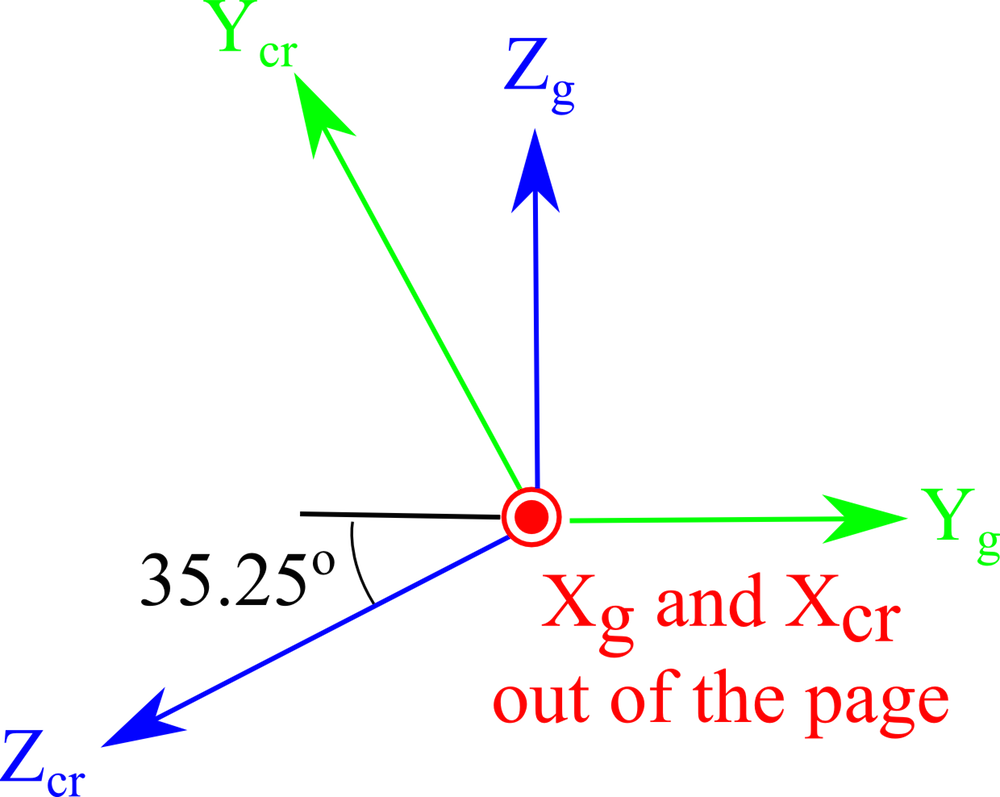
|
End on views of the axes orientation when cutting the crystal (top) and when the plate axes are oriented parallel to the global axes (bottom).
The following figure shows how the Euler angles are specified for a rotated system within COMSOL Multiphysics. An arbitrary rotated system can be specified by rotating first about the Z-axis, then about the rotated X-axis (marked as N in the figure below), and finally once again about the rotated Z-axis. This is known as a Z–X–Z scheme.
It is important to note that for cuts specified by means of multiple rotations, the rotations usually need to be applied in reverse when specifying the Euler angles. This is because COMSOL Multiphysics software specifies the orientation of the crystal with respect to the plate, whilst the standards used for cutting the plates from a crystal specify the orientation of the plate with respect to the crystal. It is straightforward to obtain equivalent Euler angles from the figure above.
| Z | X | Z | |
|---|---|---|---|
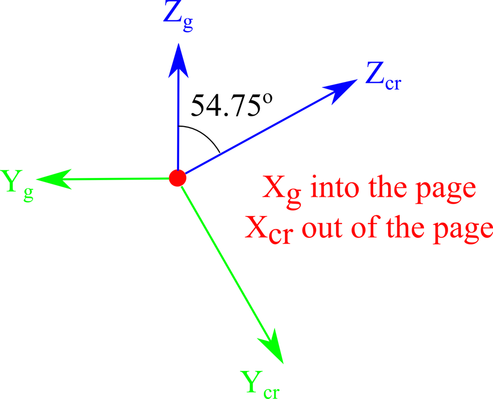
| IRE 1949 Standard | 0° | 54.75° | 0° |
| IEEE 1978 Standard | 0° | 125.25° | 0° |
Euler angles for the AT cut within the two standards. Both angles are positive for a right-handed rotation about the Z-axis.
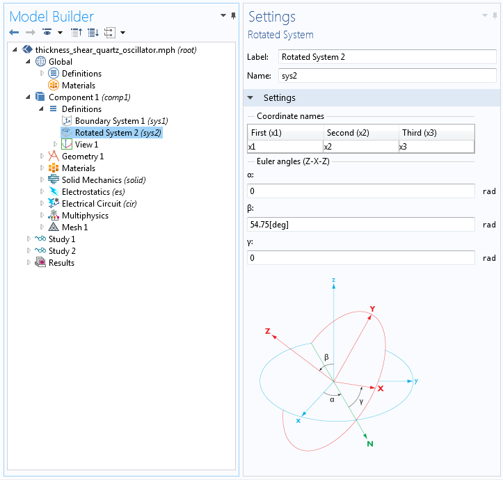
Specifying a coordinate system using Euler angles through the rotated system feature.
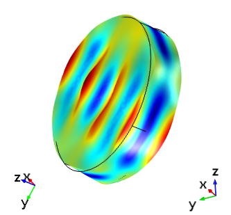
If we use the Euler angles specified in the table above to set up the thickness shear mode for a quartz disc, then we obtain the results shown below for two plates with identical excitation and orientation. What went wrong? The problem is that the thickness direction for the AT cut is defined in opposite directions within the two standards. To obtain identical results from a model using the two standards, we could either switch the polarity of the driving electrodes or try using the alternative 1979 AT cut definition proposed above: (YXlw) -35.25° 180°. As a final exercise, let’s consider how to set up the Euler angles for this doubly rotated cut.
| IRE 1949 Standard: (YXl) 35.25° | IEEE 1978 Standard: (YXl) -35.25° |
|---|---|
|
|
|
|
Thickness shear mode of an AT cut crystal for the same plate set up with the IRE 1949 and the IEEE 1978 standards with a driving frequency of 5.095 MHz. In each image, the global axis orientation is shown on the left and the crystal axis orientation is shown on the right. The top images are aligned with the global coordinates and the lower images are shown with the crystal coordinates in the same orientation as in the first figure.
Below, we have the sequence of rotations involved in defining the cut (YXlw) -35.25° 180° and the sequence of Z–X–Z Euler rotations required to rotate the global axes onto the crystal axes. The corresponding Euler angles are provided in the table below. Note that the order of the rotations for the Euler angles is the reverse of that specified in the cut definition.
| IEEE 1978 Standard: (YXlw) -35.25° 180° | |
|---|---|
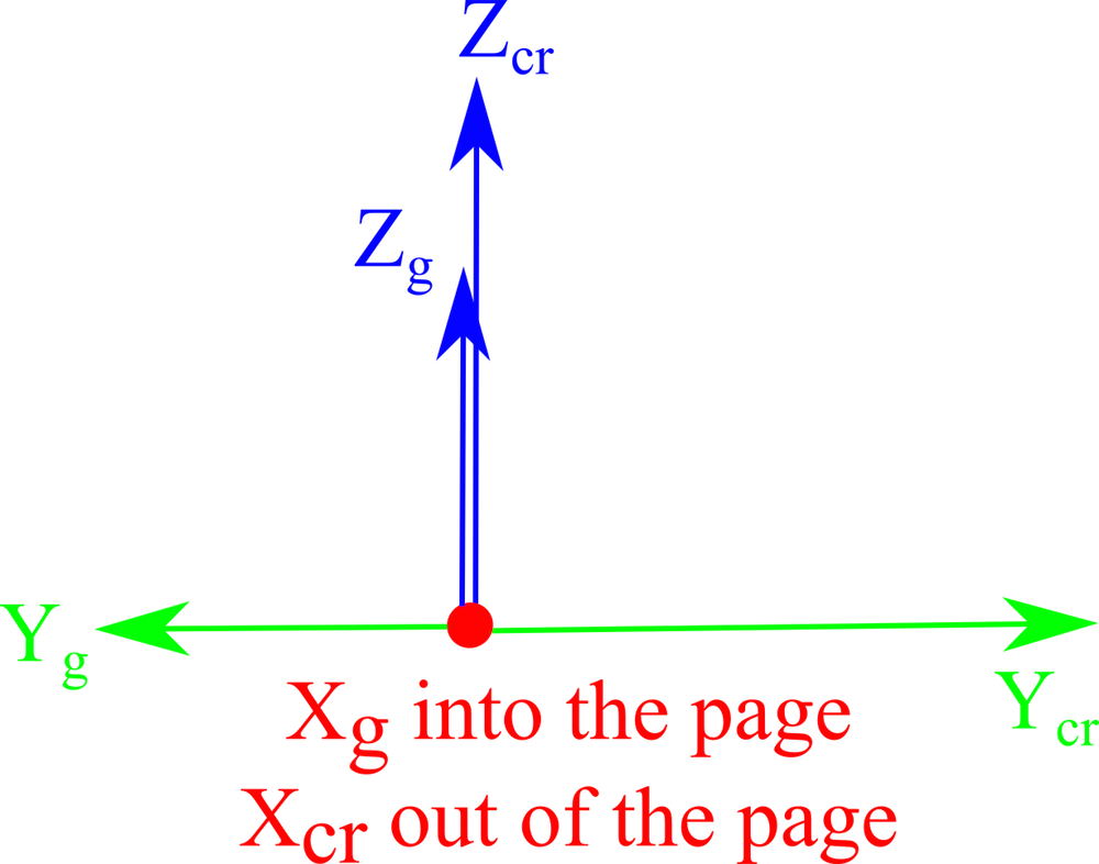
| 1.Orientate the thickness direction (Zg) along the Y-axis of the crystal (Ycr) and the width direction (Xg) along the X-axis of the crystal (Xcr). |
|
| 2. Rotate the cut by 35.35° about the l– (Xg) axis. |
|
| 3. Rotate the cut by 180° about the w– (Yg) axis. |
|
| 4. Reorientate the above figure so that the global axes are in a convenient orientation. |
|
Sequence of rotations that correspond to the cut (YXlw) -35.25° 180° in the IEEE 1978 standard.
| Equivalent Z-X-Z Euler Angles | |
|---|---|
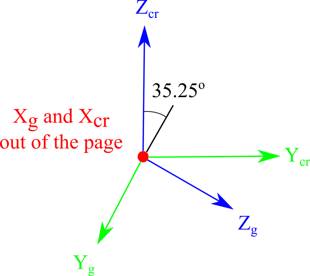
| 1. Start with the crystal and the global axes aligned. |
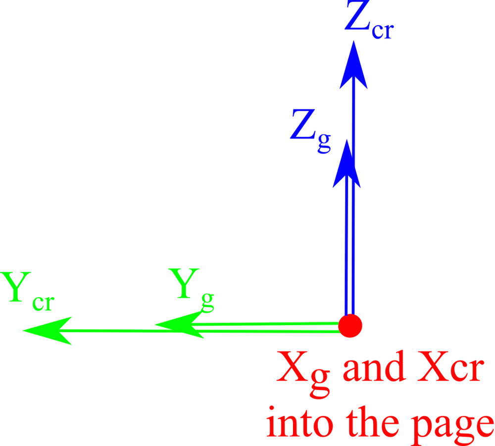
|
| 2. Rotate the crystal axes 180° about their Z-axis (Zcr). |
|
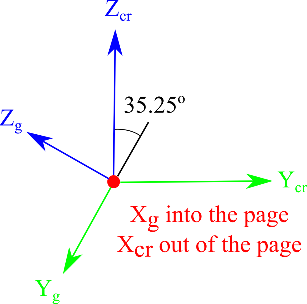
| 3. Rotate the crystal axes -54.75° about the new crystal X-axis (Xcr). |

|
Corresponding rotations that determine the Euler angles of the crystal axes with respect to the global axes.
| X | Z | X | |
|---|---|---|---|
| IEEE 1978 Standard: (YXlw) -35.25° 180° | 180° | -54.75° | 0° |
Euler angles for the cut (YXlw) -35.25° 180° in the IEEE 1978 standard. This cut corresponds to exactly the same orientation of the plate in the IRE 1949 standard AT cut definition.
Finally, the figure below shows the frequency-domain response of the cut (YXlw) -35.25° 180° in comparison to the IRE 1949 standard AT cut. As expected, the responses of the two devices are now identical.
| IRE 1949 Standard: (YXl) 35.25° | IEEE 1978 Standard: (YXlw) -35.25° 180° |
|---|---|

|
|

|
|
Thickness shear mode of an AT cut crystal set up with the IRE 1949 standard compared to the cut (YXlw) -35.25° 180° in the IEEE 1978 standard with a driving frequency of 5.095 MHz. In each image, the global axis orientation is shown on the left and the crystal axis orientation is shown on the right. The top images are aligned with the global coordinates and the bottom images are shown with the crystal coordinates in the same orientation as in the first figure.
Further Reading on Piezoelectric Materials
- Download this tutorial: Thickness Shear Mode Quartz Oscillator
- Read a related blog post: Piezoelectric Materials: Understanding the Standards


Comments (2)
AINAN LEONG
July 11, 2016I am confused that it states XZX instead of ZXZ for the Euler angles of the crystal axes with respect to the global axes.
Chien Liu
July 11, 2016 COMSOL EmployeeDear Ainan,
COMSOL adopts the Z-X-Z convention for the Euler angles as explained in the text and as shown in the screenshot captioned “Specifying a coordinate system using Euler angles through the rotated system feature”. If there are further questions please do not hesitate to contact us at
support@comsol.com
Sincerely,
Chien