

In a previous blog entry, we introduced meshing considerations for linear static problems. One of the key concepts there was the idea of mesh convergence — as you refine the mesh, the solution will become more accurate. In this post, we will delve deeper into how to choose an appropriate mesh to start your mesh convergence studies for linear static finite element problems.
What Are the Different Element Types
As we saw earlier, there are four different 3D element types — tets, bricks, prisms, and pyramids:
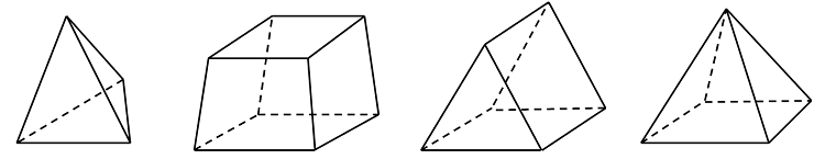
These four elements can be used, in various combinations, to mesh any 3D model. (For 2D models, you have triangular and quadrilateral elements available. We won’t discuss 2D very much here, since it is a logical subset of 3D that doesn’t require much extra explanation.) What we haven’t spoken in-depth about yet is why you would want to use these various elements.
Why and When to Use the Elements
Tetrahedral elements are the default element type for most physics within COMSOL Multiphysics. Tetrahedra are also known as a simplex, which simply means that any 3D volume, regardless of shape or topology, can be meshed with tets. They are also the only kind of elements that can be used with adaptive mesh refinement. For these reasons, tets can usually be your first choice.
The other three element types (bricks, prisms, and pyramids) should be used only when it is motivated to do so. It is first worth noting that these elements will not always be able to mesh a particular geometry. The meshing algorithm usually requires some more user input to create such a mesh, so before going through this effort, you need to ask yourself if it is motivated. Here, we will talk about the motivations behind using brick and prism elements. The pyramids are only used when creating a transition in the mesh between bricks and tets.
It is worth giving a bit of historical context. The mathematics behind the finite element method was developed well before the first electronic computers. The first computers to run finite element programs were full of vacuum tubes and hand-wired circuitry, and although the invention of transistors led to huge improvements, even the supercomputers from 25 years ago had about the same clock speed as today’s fashion accessories.
Some of the first finite element problems solved were in the area of structural mechanics, and the early programs were written for computers with very little memory. Thus, first-order elements (often with special integration schemes) were used to save memory and clock cycles. However, first-order tetrahedral elements have significant issues for structural mechanics problems, whereas first-order bricks can give accurate results.
As a legacy of these older codes, many structural engineers will still prefer bricks over tets. In fact, the second order tetrahedral element used for structural mechanics problems in the COMSOL software will give accurate results, albeit with different memory requirements and solution times from brick elements.
The primary motivation in COMSOL Multiphysics for using brick and prism elements is that they can significantly reduce the number of elements in the mesh. These elements can have very high aspect ratios (the ratio of longest to shortest edge), whereas the algorithm used to create a tet mesh will try to keep the aspect ratio close to unity. It is reasonable to use high aspect ratio brick and prism elements when you know that the solution varies gradually in certain directions or if you are not very interested in accurate results in those regions because you already know the interesting results are elsewhere in the model.
Meshing Example 1: Wheel Rim
Consider the example of a wheel rim, shown below.
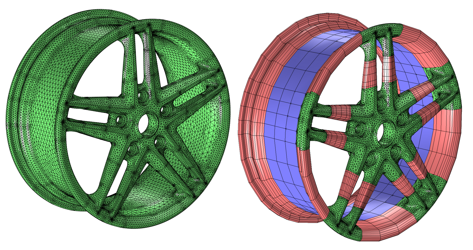
The mesh on the left is composed only of tets, while the mesh on the right has tets (green), bricks (blue), and prisms (pink), as well as pyramids to transition between these elements. The mixed mesh uses smaller tets around the holes and corners, where we expect higher stresses. Bricks and prisms are used in the spokes and around the rim. Neither the rim nor the spokes will carry peak stresses (at least under a static load), and we can safely assume a relatively slow variation of the stresses in these regions.
The tet mesh has about 145,000 elements and around 730,000 degrees of freedom. The mixed mesh has close to 78,000 elements and roughly 414,000 degrees of freedom, taking about half as much time and memory to solve. The mixed mesh does take significant user interaction to set up, while the tet mesh requires essentially no user effort.
Note that there is not a direct relationship between degrees of freedom and memory used to solve the problem. This is because the different element types have different computational requirements. A second-order tet has 10 nodes per element, while a second-order brick has 27. This means that the individual element matrices are larger, and the corresponding system matrices will be denser, when using a brick mesh. The memory (and time) needed to compute a solution depends upon the number of degrees of freedom solved for, as well as the average connectivity of the nodes, and other factors.
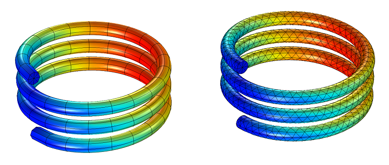
Meshing Example 2: Loaded Spring
Another example is shown below. This time, it’s a structural analysis of a loaded spring. Since the deformation is quite uniform along the length of the helix of the spring, it makes sense to have a mesh that describes the overall shape and cross section, but relatively stretched elements along the length of the wire. The prism mesh has 504 elements with 9526 degrees of freedom, and the tet mesh has 3652 elements with 23,434 degrees of freedom. So although the number of elements is quite different, the number of degrees of freedom is less so.
Meshing Example 3: Material on a Wafer
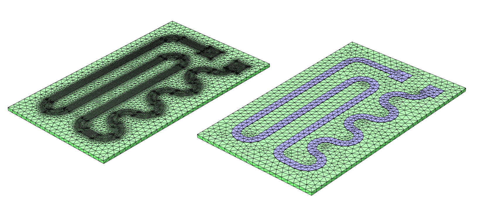
The other significant motivation for using brick and prism elements is when the geometry contains very thin structures in one direction, such as an epitaxial layer of material on a wafer, a stamped sheet metal part, or a sandwiched composite.
For example, let’s look at the figure below of a thin trace of material patterned onto a substrate. The tet mesh has very small elements in the trace, whereas the prism mesh is composed of thin elements in this region. Whenever your geometry has layers that are about 10-3 or so times thinner than the largest dimension of the part, the usage of bricks and prisms becomes very highly motivated.
Additional Examples
It is also worth pointing out that the COMSOL software offers many boundary conditions that can be used in lieu of explicitly modeling thin layers of materials. For example, in electromagnetics, the following four tutorial models consider thin layers of material with relatively high and low conductivity, and relatively high and low permeability:
- Electric Shielding Comparison
- Contact Impedance Comparison
- Dielectric Shielding Comparison
- Thin Low Permittivity Gap Comparison
Similar types of boundary conditions exist in most of the physics interfaces. Usage of these types of boundary conditions will avoid the need to mesh such thin layers entirely.
Lastly, the above comments apply only to linear static finite element problems. Different meshing techniques are needed for nonlinear static problems, or if we are modeling time-domain or frequency-domain phenomena.
Concluding Thoughts
To summarize, here is what you should keep in mind when starting your meshing of linear static problems:
- Use tets if you can; they require the least user interaction and support adaptive mesh refinement
- If you know the solution varies slowly in one or more directions, use bricks or prisms with high aspect ratios in those regions
- If the geometry contains thin layers of material, use bricks or prisms or consider using a boundary condition instead
- Always perform a mesh refinement study and monitor the memory requirements and convergence of the solution as you refine the mesh
Further Reading
- Want to learn more about the meshing capabilities of COMSOL Multiphysics? Browse all of our related blog posts


Comments (13)
Ivar Kjelberg
November 5, 2013Hi Walter
Thanks for nice clear examples 🙂
Robert Koslover
November 15, 2013Thanks for the guidance. I wonder if you could expand your essay to comment on the utility, in various cases, of employing large numbers of small, but low-order elements vs. using small numbers of larger, but higher-order elements?
Walter Frei
November 18, 2013 COMSOL EmployeeDear Robert,
It depends very much on how you define utility. Second-order elements represent the best compromise between growth in memory requirements and accuracy, and are the default in most physics interfaces. The most common exceptions are problems involving chemical species transport and when solving for a fluid flow field, which use 1st order elements by default because of the convection-dominated nature of the problem.
Oscar Diaz
November 13, 2014Dear Walter,
Thanks for your interesting blog entrance, has been of a great help. Right now I’m struggling a lot with a simple stationary 3D electrostatics model that I have to run within an iterative loop commanded from Matlab. The problem that always kills my simulation after a few hours is the mesh creating point while the program has advancede a few steps.
After trying several different techniques, I came to realize that the detail I am using for certain edges is affecting drastically the way the free-tets are created next to this ‘detail’ edges or boundaries.
Could you tell us your experience while using free-tets meshing in combination with certain edge or free-triangular elements in a 3D meshing?
Walter Frei
November 13, 2014 COMSOL EmployeeDear Oscar,
You will find virtual operations helpful in such circumstances. Please see, for example, this model:
http://www.comsol.com/model/virtual-operation-on-a-wheel-rim-geometry-14317
Ravinder Banyal
March 30, 2016Hi
I do know if this is right place to post some quarries. Since this blog is related to meshing related issues in COMSOL, I am hoping someone will be able to comment on the problem that I am facing. I have a 3D geometry with two objects. Two objects are in tangential contact. One object is a cylinder which is supported by another object having V-shape. In 2D (x-y) plane you can think of it as letter ‘o’ dropped inside the two inclined lines of the letter ‘V’. Letter ‘o’ makes point contact with each inclined lines of the letter ‘V’. I get my 3D-object (cylinder+V-block) by extruding my 2D geometry along the Z-direction. The point contacts in 2D therefore transform to line contacts in 3D. When I do the meshing, I get the error with the message: “Failed to generate mesh for domain. Failed to respect boundary element edge on geometry face.” The mesh size along the contact lines between cylinder and V-block seems diminishingly small. I do not really need small mesh along the contact lines, but since the geometry is such that I cannot ignore it altogether. Could someone advise how to address issues where two objects/domains are in only in tangential contact with each other? Thanks for your time in advance.
Bridget Cunningham
April 1, 2016 COMSOL EmployeeHello Ravinder,
Thank you for your comment.
For questions specific to your modeling work, please contact our support team.
Online support center: https://www.comsol.com/support
Email: support@comsol.com
Zhijie Ma
September 18, 2016Hi, thanks for the great explanation. But in Mesh, we cannot directly select the element to be prism or bricks, we can only select tetrahedral, right? Do we use Swept to get prism or bricks element? Is there any other way to do it? Thanks.
Walter Frei
September 19, 2016 COMSOL EmployeeHello Zhijie,
That’s correct, you’ll want to use the Swept mesh functionality to create these other element types. Boundary Layer meshing will also create non-tetrahedral elements at boundaries.
You may also find these articles helpful:
https://www.comsol.com/blogs/improving-your-meshing-with-swept-meshes/
Hafiz Chishti
March 8, 2018Hello Walter,
Hope you are fine. I want to learn how to apply transition between pyramids and tets at a boundary or desired location? Please guide what are the steps and how can one do this. I have seen online that comsol 5.3 has built in capability to apply this transition, but unfortunately, we at my university have comsol 4.4.
Regards
Anju Gupta
June 17, 2018Hi
I facing problem in meshing Triboelectric nanogenerator.
Structure like
Four sliding
Air block surrounding the four sliding plate 1000X1000X500 mm3
position at x=-400 y=-400,z=-200
top electode 100X100X0.01mm3 at x=y=z=0
PTFE 100X100X0.22mm3 at x=y=0 z=0.01
Nylon 100X100X0.22 mm3 at x=50mm y=0 z=0.23
top electode 100X100X0.01mm3 at x=50mm y=0 z=0.45
physics electrostatics ,stationary study
Please let me know which type of meshing can be used for this struture.
I have tried with, triangular,swept,mapped ,tetrahedral but it fails.
Anju
Caty Fairclough
August 7, 2018Hi Anju and Hafiz,
Thanks for your comments.
For your questions, I would suggest contacting our Support team.
Online Support Center: https://www.comsol.com/support
Email: support@comsol.com
Amr Al Abed
January 29, 2020Dear Walter,
Thanks for your informative series of blog posts on meshing.
You mention that different meshing techniques are needed for nonlinear static problems, or if modeling time-domain phenomena. Just wondering if you can comment on how such phenomena would affect the selection of the mesh element type?
For example, I often setup the mesh and run pilot static simulations, then move on to time-domain simulations.
Are there any issues with respect to the element type (or other mesh settings) I should consider when making this transition?
Best regards
Amr