
Modeling geometries with high aspect ratios can be one of the more challenging tasks for the finite element analyst. You want to have a mesh that will accurately represent the geometry and the solution, but you do not want too many elements, as solving your models would then require excessive computational resources. Here, we will look at using swept meshing to generate efficient and accurate finite element meshes in the context of some common modeling cases.
To Begin, a Piping Network Example
Suppose you are tasked with computing the fluid flow through a network of pipes, as depicted below. You can see that there are many bends with long straight sections in between.
A piping network. Image by Hervé Cozanet, via Wikimedia Commons.
The geometry for a fluid flow model of just one pipe in this network might look like the image below.
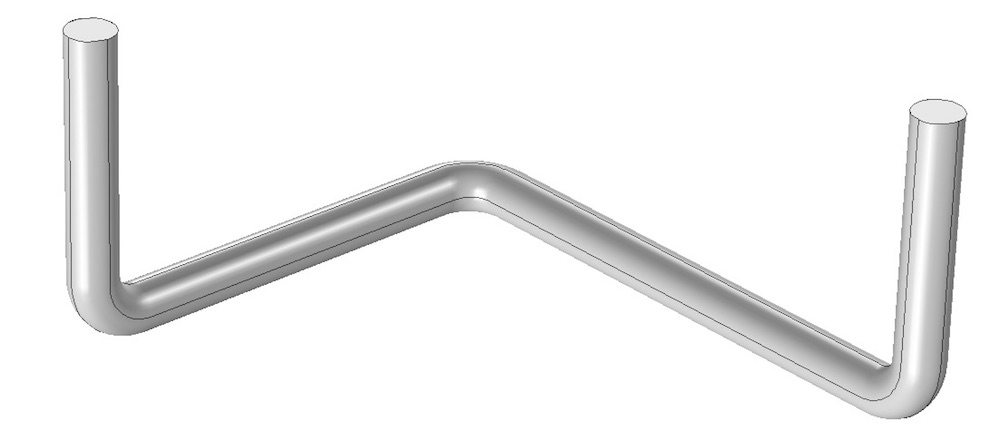
A CAD model of a pipe volume for fluid flow analysis.
If you go ahead and mesh this geometry with just the default Physics-Controlled Mesh capability, you will obtain a mesh like that pictured below. Note that the boundary layer mesh is applied to the pipe walls and that the mesh is otherwise quite uniform in size within the long, straight sections of the pipe.
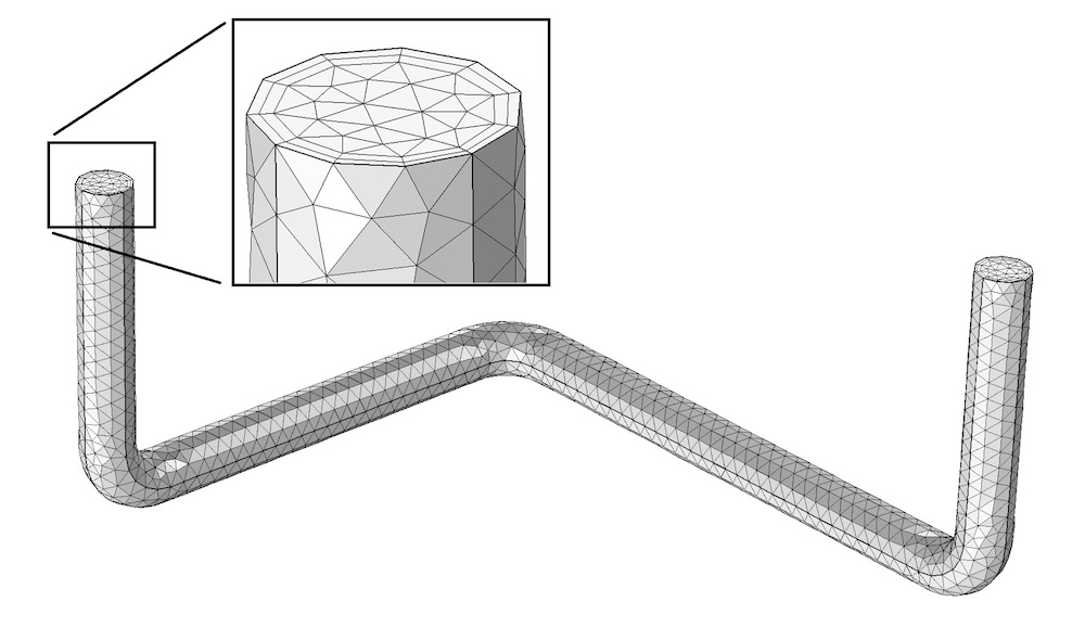
The default finite element mesh for this fluid flow problem includes a boundary layer mesh on all no-slip boundaries.
An experienced fluid flow analyst would immediately recognize that the flow field in the long, straight sections will be primarily parallel to the pipe and vary quite gradually along the axis. Meanwhile, the variation of the velocity along the cross section and around the bends will be significant. We can exploit this foreknowledge of the solution to partition the geometry into various domains.
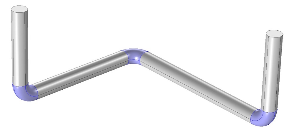
The pipe domain is partitioned into several subdomains, which are shown in different colors.
Once the geometry is partitioned, we can apply a Free Tetrahedral mesh feature. This mesh should only be applied to one of the domains along the length of the pipe; a domain that represents a bend (depicted below). Note that the Boundary Layers mesh feature is not yet applied.
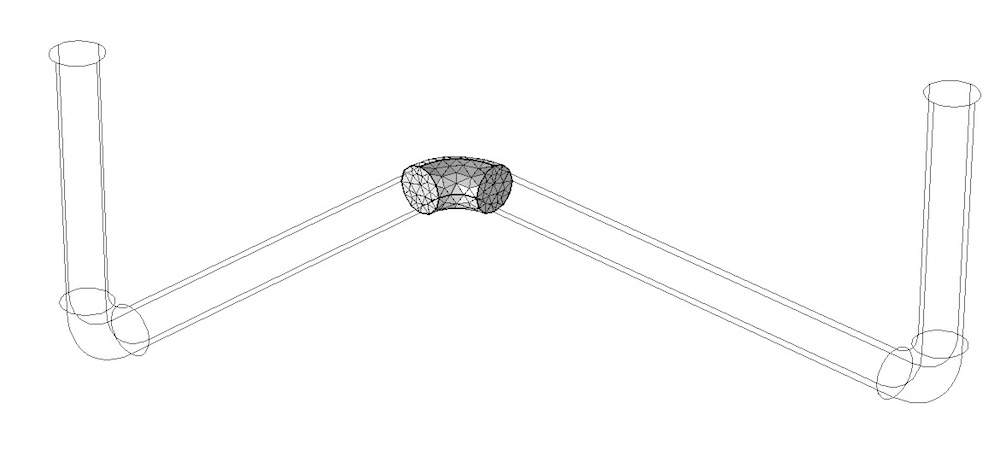
A tetrahedral mesh is applied to only one of the domains.
From this one meshed domain, we can now use the Swept mesh functionality in the straight sections, as illustrated below. It is also possible to specify a Distribution subfeature to the Swept feature to explicitly control the element distribution and set up a nonuniform element size along the length. Since we anticipate that the flow will vary gradually along the length, the elements can be quite stretched in the axial direction.
The swept mesh along the straight sections also has a nonuniform element distribution.
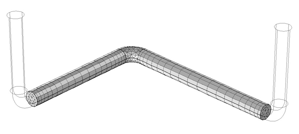
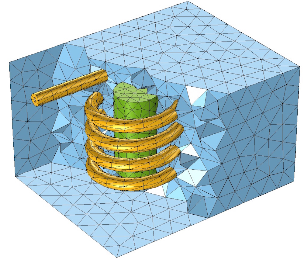
We can now apply a tetrahedral mesh to nest the two bent sections and sweep the remaining straight sections. The last step of the meshing sequence is to apply the Boundary Layers mesh feature.
The combination of a tetrahedral and swept mesh with the boundary layers applied at the walls.
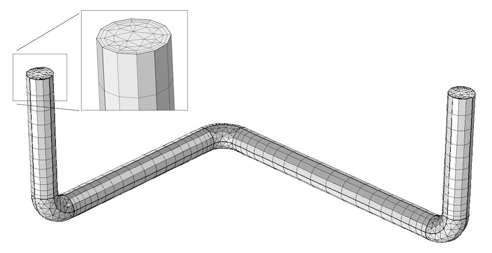
From the above images, we can observe that the swept mesh can significantly reduce the size of the model for this fluid flow problem. Our Flow Through a Pipe Elbow tutorial is one example in which this swept meshing technique is used.
Our Second Example: A Coil and Its Surroundings
Shifting gears, let’s now consider an inductive coil similar to the one pictured below.
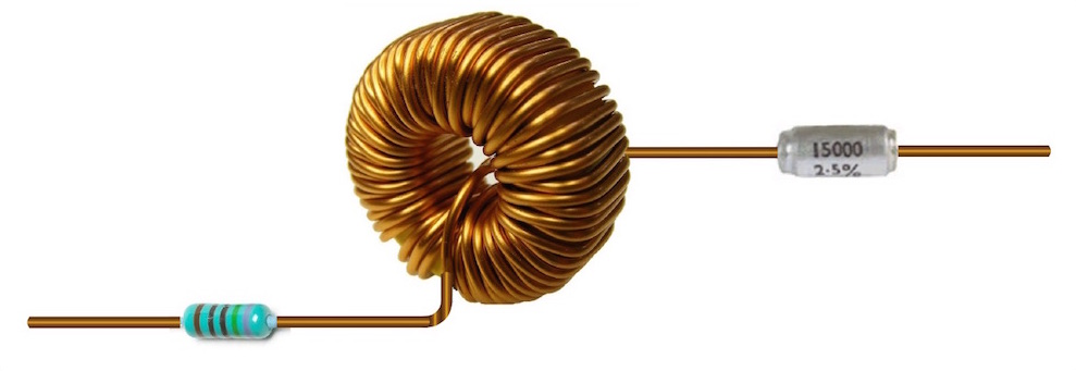
An inductive coil. Image by Spinningspark, via Wikimedia Commons.
This coil consists of a long wire with quite gradual bends. If tasked with computing the inductance, we would also need to consider the surrounding air and the magnetic core materials. The geometry for such a model and the default mesh might look like the image below.
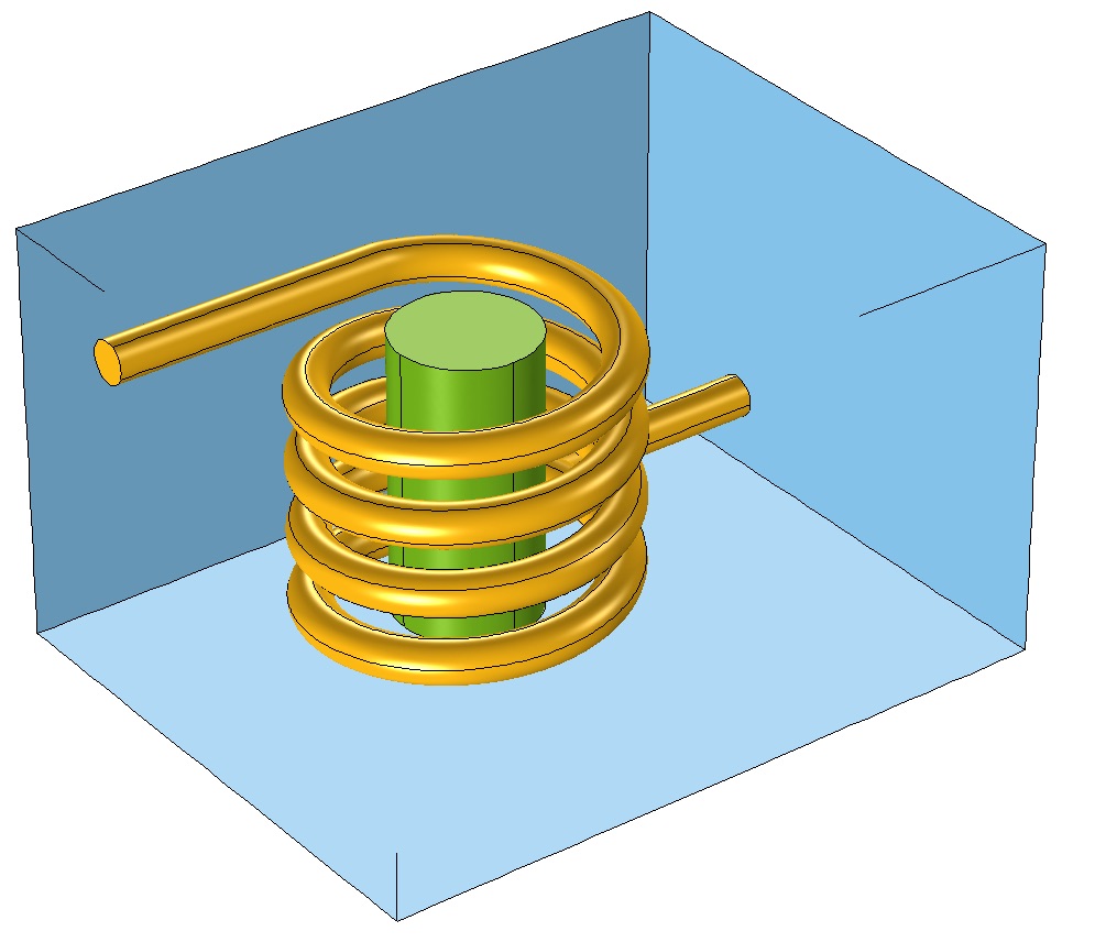
A coil surrounding a magnetic core in an air domain.
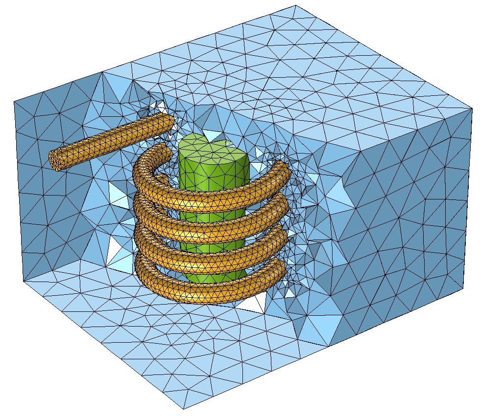
The default Free Tetrahedral mesh feature is applied to the entire model.
You’ve probably already recognized that the coil itself is an excellent candidate for swept meshing. The coil is long and uniform in cross section. As such, we can begin with a triangular surface mesh at one end and then sweep it along the entire length of the coil to create triangular prismatic elements.
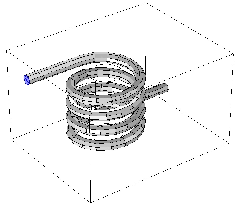
A triangular mesh (represented in blue) is applied to the cross-sectional surface at one end of the coil and then swept along the entire length.
We do, however, still need a volumetric mesh of the surroundings. This surrounding volume is amenable to only tetrahedral meshing, not swept meshing. A volume that is to be meshed with tetrahedral elements can only have triangular surface elements on all of its boundaries. Thus, we must first add a Convert feature to the mesh sequence and apply it to the surfaces between the coil and its surroundings. The operation is designed to split the elements touching the boundaries such that triangular face elements are created.
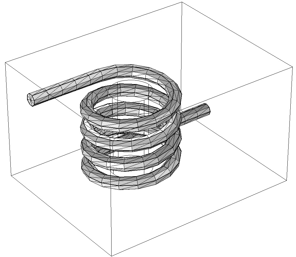
The convert operation introduces triangular elements on the boundaries of the coil.
The remaining domains are meshed with tetrahedra.
From the above image, we can see that fewer elements are used to describe the coil than in the default mesh settings. A similar example is the Anisotropic Heat Transfer Through Woven Carbon Fibers tutorial, which considers a combination of swept meshing and tetrahedral meshing of the surroundings (albeit with different physics involved).
Lastly, a Microelectromechanical System Example
Finally, let us consider a microelectromechanical system (MEMS) structure that is composed of microscale structural features that deflect. If different electrical potentials are applied to different objects, a perturbation of the structure will be measurable through a change in capacitance. A change in applied potentials can deform the system. Such an effect is exploited in devices like comb drives, accelerometers, and gyroscopes.
A MEMS cantilever beam at resonance. Image by Pcflet01, via Wikimedia Commons.
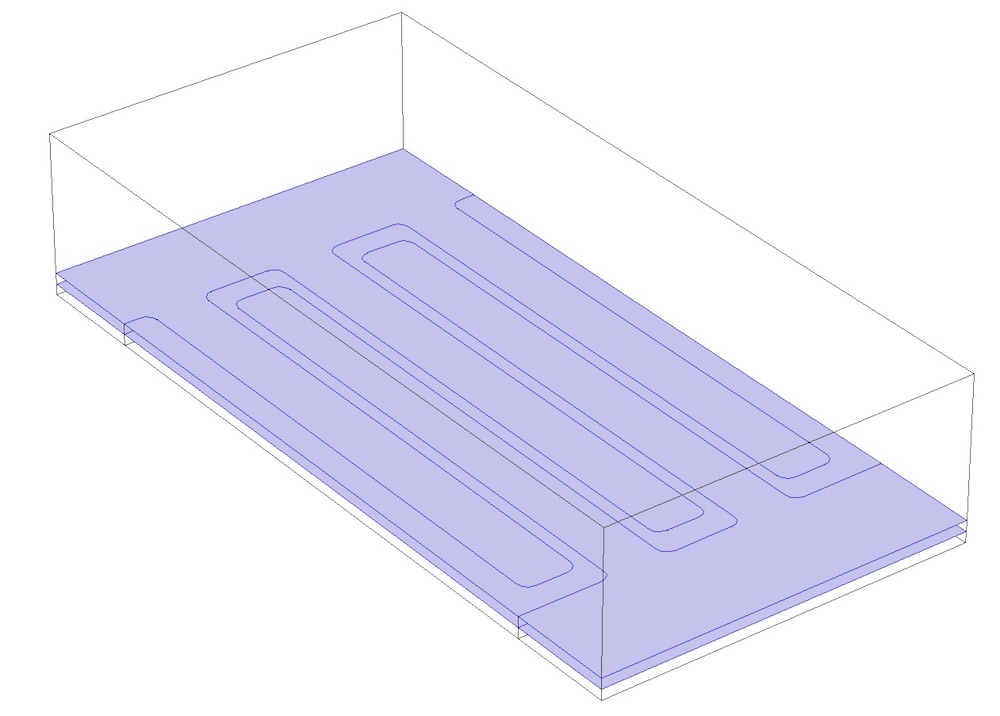
A common characteristic of such MEMS structures is that they are composed of various thin planar layers that need to be meshed along with the surrounding air domain. The gaps between structures may also be quite slender. A simplified model for part of such a MEMS structure might appear similar to the model shown below, with interleaved fingers.
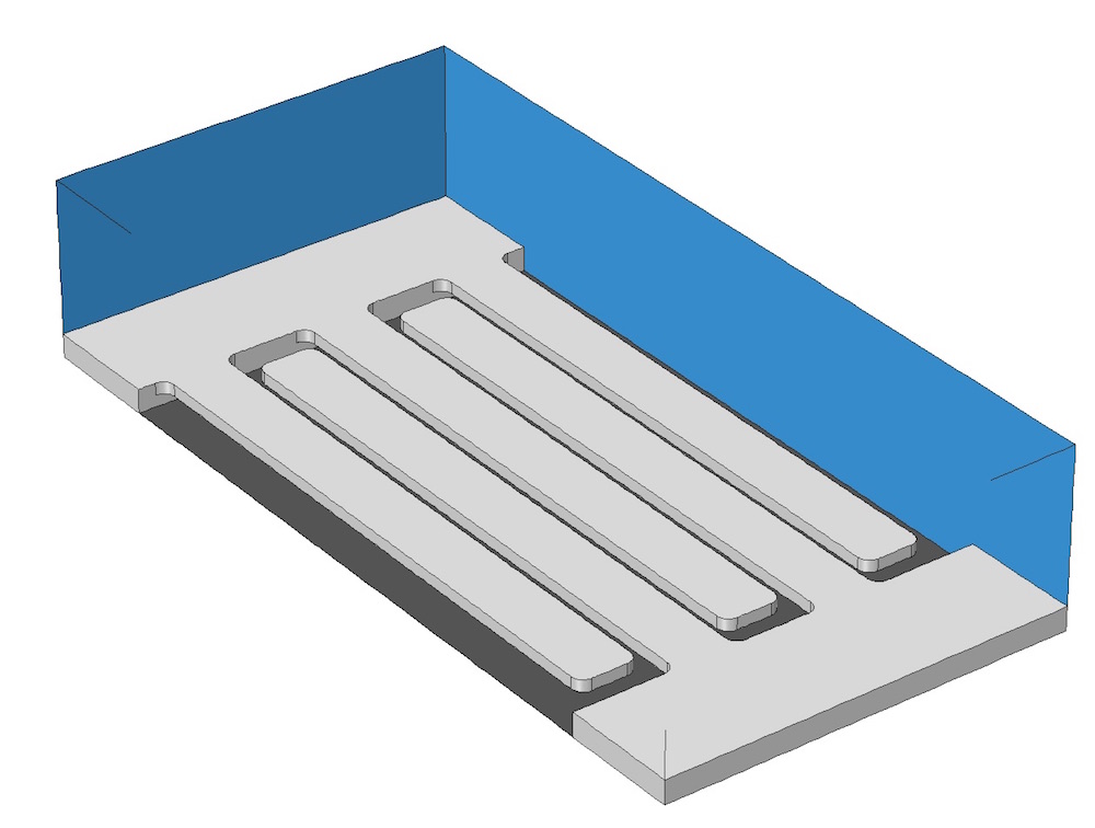
A simplified model representing part of a typical MEMS structure.
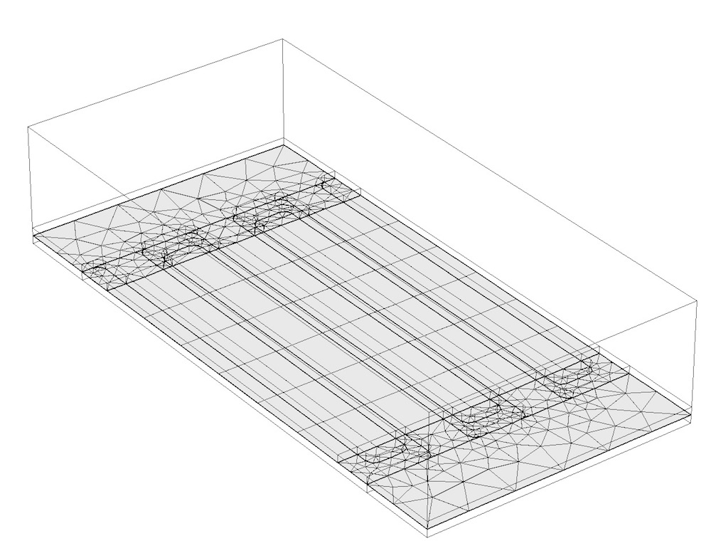
When using the default mesh settings, small elements will be inserted in the narrow air gaps between the parts (illustrated below). However, we do know that the fingers on either side will be at different potentials and that the gap between the straight sections of the fingers and the ground plane will have a uniform electric field.
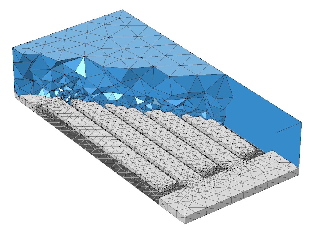
The default mesh settings show smaller elements than those that are needed in regions where we know the electric field will be nearly uniform.
This present structure is actually not amenable to swept meshing, as there are no domains in this model that have a uniform cross section. But, if we introduce some partitioning planes, we can break this domain up into prismatic domains that are amenable to swept meshing. We will first introduce two partitioning planes — one at the top and one at the bottom surface of the fingers — that will partition both the air domain and the two solid domains. We add these planes as Work Plane features to the geometry sequence and they are used as input by the two Partition Object features that divide the solids.
Two planes are introduced that partition both the air and the solid domains.
It is then possible to introduce additional partitioning planes, as shown below, to delineate the long, straight sections of the fingers. This is important because we know the electric fields and displacements will vary quite gradually in these regions.
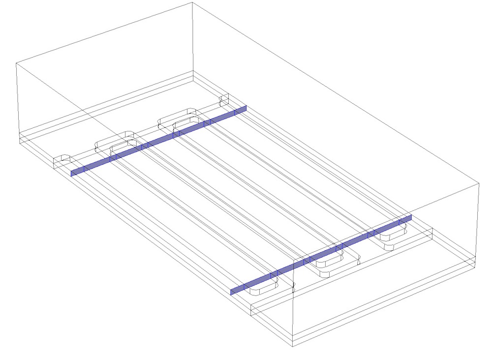
Two additional planes divide the fingers into prismatic domains.
Now we can begin the meshing process using the Mapped mesh feature on the new rectangular surfaces introduced by the partitioning. The nonrectangular faces on the same plane can be meshed with triangular elements, as illustrated below.
A surface mesh applied to one of the partitioning planes.
The surface mesh can be used as the starting point for the swept mesh, which can be applied to the two layers of the thin domains — the fingers and the air gaps between the fingers and the ground. The air domain can be meshed with tetrahedral elements after a convert operation is applied to the adjacent rectangular element faces.
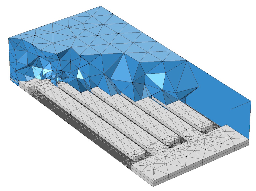
The final mesh consists of a combination of free and swept meshes.
We can observe that the number of total elements in the finite element model has been reduced. For an example demonstrating this technique of partitioning planes and swept meshing, please see our Surface Micromachined Accelerometer tutorial.
A Summary of Swept Meshes
Swept meshing is a powerful technique for minimizing the computational complexity of many classes of COMSOL Multiphysics models. By using your engineering judgment and knowledge to address each problem, you can obtain high-accuracy results quickly and at relatively lower computational costs than with default mesh settings.
While you, of course, do not always need to use this approach, you should consider applying it to cases where your geometry has high aspect ratios, there are relatively thin or thick regions, and you are reasonably certain that the solution will be represented well by the swept mesh.
In conjunction with this topic, here are some additional blog posts to read:
- Improving Your Meshing with Partitioning
- Using Virtual Operations to Simplify Your Geometry
- How Much Memory Is Needed to Solve Large COMSOL Models?
- Parameterizing the Dimensions of Imported CAD Files
- Meshing Considerations for Linear Static Problems
- Meshing Your Geometry: When to Use the Various Element Types
- Meshing Considerations for Nonlinear Static Finite Element Problems


Comments (7)
Vishwas Nesarikar
September 2, 2015Nice explanation. Thank you.
Ziwei Li
September 15, 2015This is a really great explanation. Thank you for your work! Here I have a question about mesh covert feature. Sometimes you use the feature after sweep mesh, then the entire mesh quality will be reduced a lot( observe from mesh statistics, say the minimum quality reduce from 0.2 to 0.02 ). I think this is quite easy to occur when you have this coil shape geometry. How to solve this problem?
Walter Frei
September 22, 2015 COMSOL EmployeeDear Ziwei,
Please keep in mind that a low element quality is not necessarily indicative of a mesh that will return a low accuracy solution. (and neither is a high element quality an indication that the mesh will return a very accurate solution.) You can get high accuracy results even if the mesh quality metric itself is low, as long as the solution field varies gradually in the direction of the mesh anisotropy.
So it would not be correct to call this a problem in and of itself, it is just that the element quality metric returns a lower value when you convert the mesh. Regardless of the element quality, you will always want to perform a mesh refinement study (http://www.comsol.com/blogs/meshing-considerations-nonlinear-static-finite-element-problems/)
Joao Moura
January 28, 2016The images from this post are not showing. Could you please correct that?
amine el kacimi
September 27, 2016Dear Walter,
Thank you for this great post. I still have one question about 2D simulation. Does this methode apply to high aspect ratio geometries in 2D models?
I believe we cannot use the swept meshing in 2D models. Is there any alternative?
Thank you in advance.
Walter Frei
September 27, 2016 COMSOL EmployeeDear Amine,
In 2D, you can use the Mapped Mesh functionality.
Best Regards,
Rebeka Sultana
July 29, 2025Hi,
I would like to know is there any guideline/user manuals to plot the 3D volume mesh as shown in the above blog? When I am trying to plot the mesh, it is always showing void inside, that is only the surface mesh is plotted though the geometry is solid and the level is selected as volume.