Bulk Chemicals
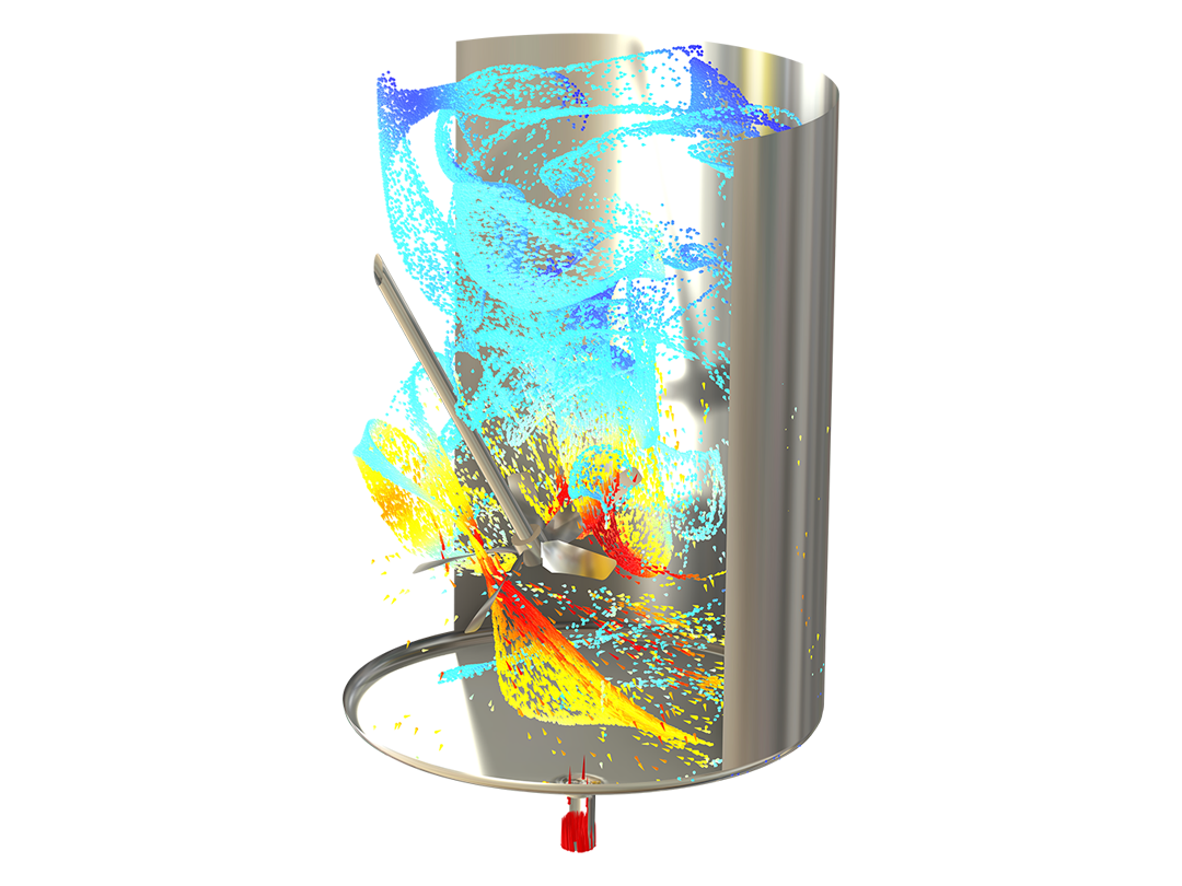
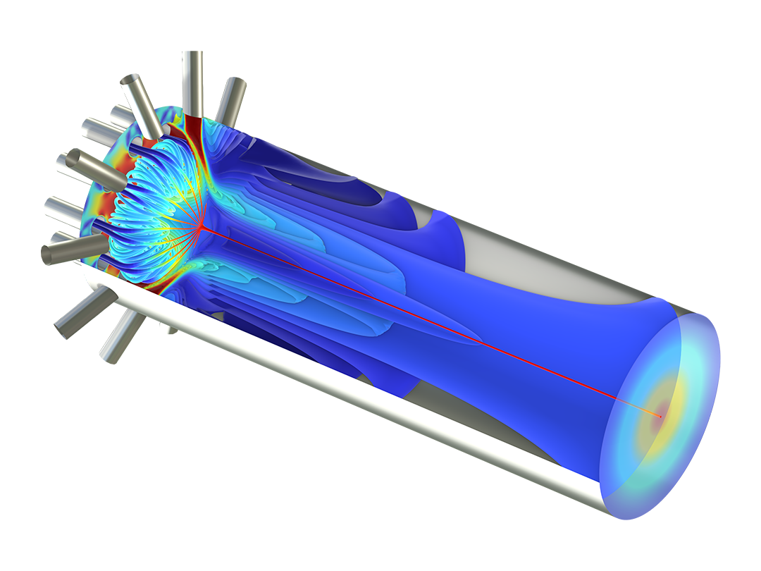
Simulate space-dependent continuous stirred mixers and tank reactors for high flow rates.
Understand and Optimize Chemical Processes and Designs
Mathematical models help scientists, developers, and engineers understand designs of reacting systems as well as the processes and phenomena involved. The Chemical Reaction Engineering Module, an add-on to the COMSOL Multiphysics® software platform, includes functionality for creating, inspecting, and editing chemical equations, kinetic expressions, thermodynamic functions, and transport equations. After developing a validated model, the module can be used for studying different operating conditions and designs of reacting systems and transport phenomena. Solving the model equations for different inputs leads to a true understanding of the studied system.
Contact COMSOL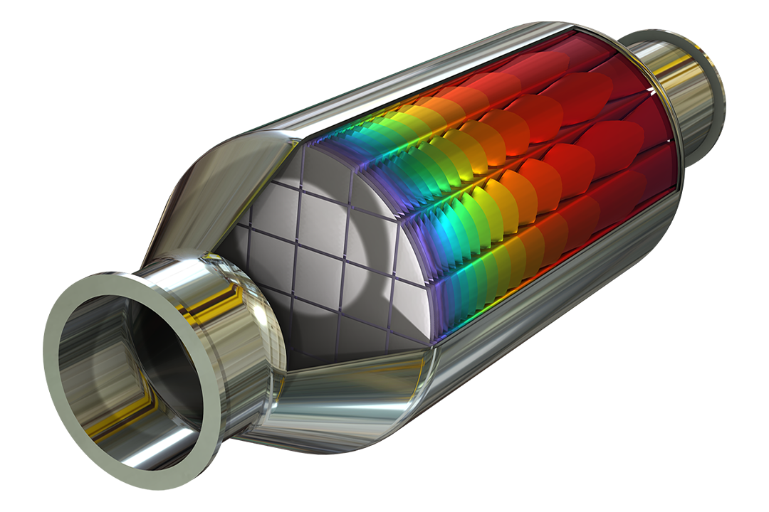
Model transport phenomena and chemical reactions relevant to various industries with the COMSOL® software.
Simulate space-dependent continuous stirred mixers and tank reactors for high flow rates.
Study reaction kinetics and mass transport to design processes for the fine chemicals industry, such as extraction and distillation processes.
Optimize designs and processes for biotech and pharmaceutical applications by modeling the transport and reactions of drugs in tissue and across membranes.
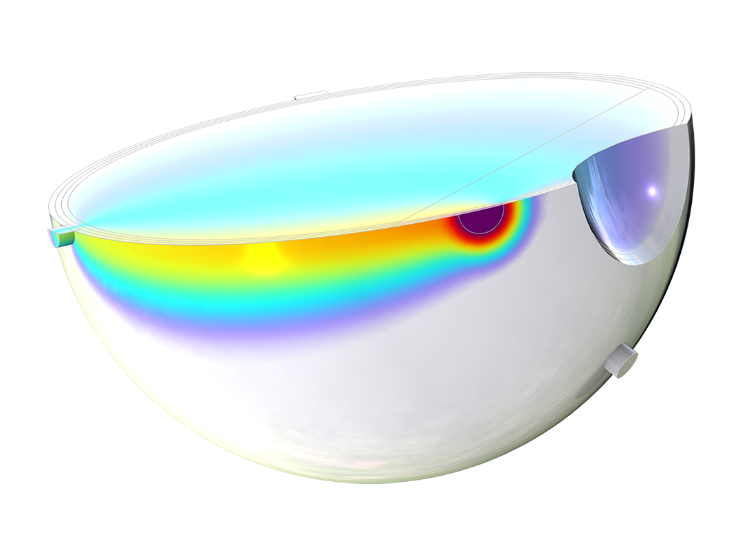
Investigate heat transfer and reactions during pasteurization or study other processes in the food industry, such as drying, cooking, and fermentation.

Model catalyst deactivation and pressure losses in packed bed reactors.
Investigate the elimination of pollutants in effluent streams using separation processes such as adsorption, membrane filtration, and crystallization.
Study the rate of chemical vapor deposition (CVD) as a function of fluid flow and reaction kinetics in a CVD boat reactor.
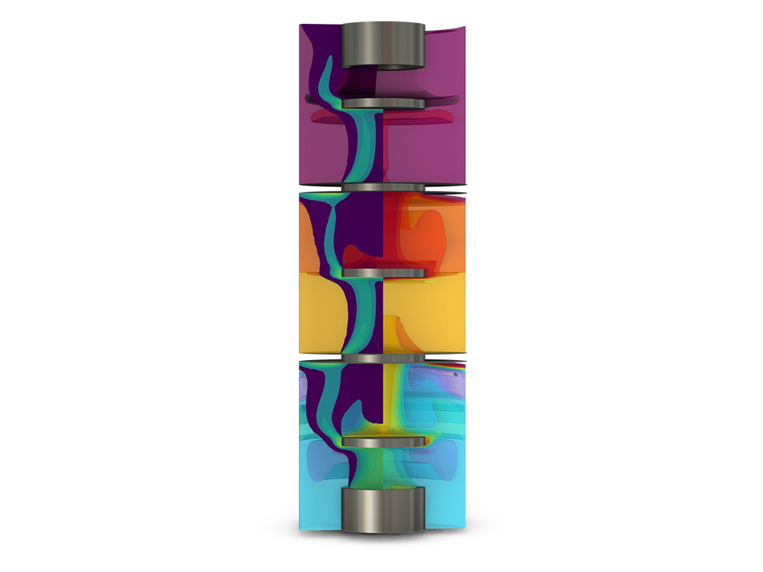
Design static mixers for laminar flow —such as mixers for epoxies, silicones, and acrylic resins — that achieve the desired emulsion properties.
Study different aspects of polymer production processes, such as the dissolution of reactants, polymerization reactions, curing reactions, and filtration of the product stream.
Investigate optimal process conditions and reactor design for the production of fertilizers, pesticides, and herbicides.
Realistic descriptions of reacting systems in scientific and engineering studies often need to incorporate both transport phenomena and chemical reactions. The Chemical Reaction Engineering Module includes features for following the typical workflow in chemical and chemical engineering investigations, which involves the following incremental steps:
This workflow can be applied in many different fields that involve chemical reactions and for modeling at different scales, such as for the modeling of nanotechnology and microreactors as well as for environmental studies and geochemistry. The entire process, from defining models to the presentation of the results, is documented in the software for transparency and reproducibility.
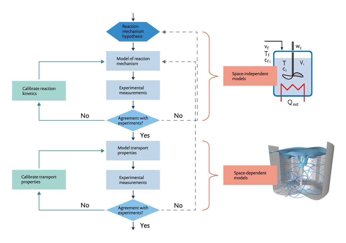
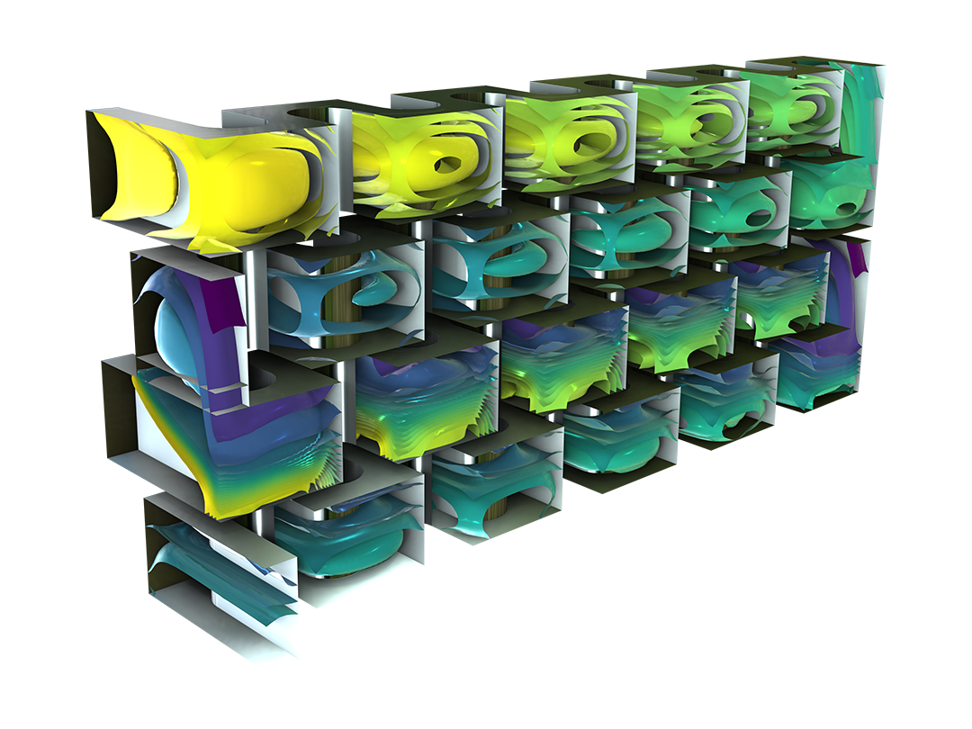
The Chemical Reaction Engineering Module provides a built-in workflow for simulating perfectly mixed systems in 0D followed by transport phenomena in 2D and 3D.
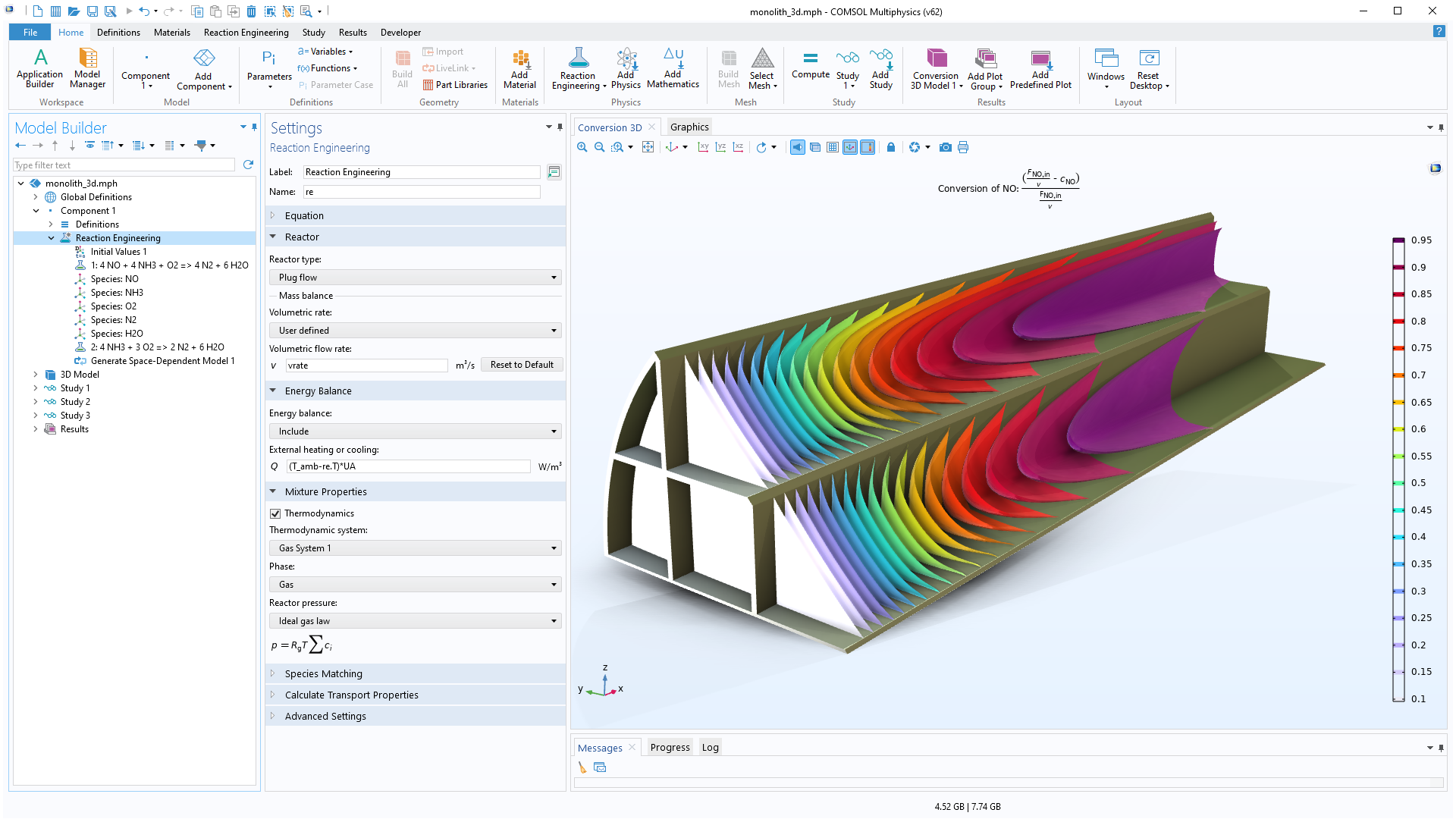
The first step in modeling any system is to establish the material balances. With the Reaction Engineering interface, chemical equations can be input in order to automatically obtain the material balance equations for the chemical species in the system and the energy balance equations for the system. When a reaction mechanism is added, the kinetic expressions as a function of the species concentrations are derived automatically from the mass action law for elementary steps. Users can also input their own analytical expressions for the reaction rate as a function of the species concentrations and temperature.
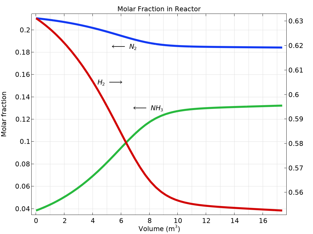
The material balances and the reaction kinetic expressions give the ordinary differential equations that are formulated automatically by the software. For a perfectly mixed batch reactor, the solution to the equations gives the composition of the reacting mixture over time.
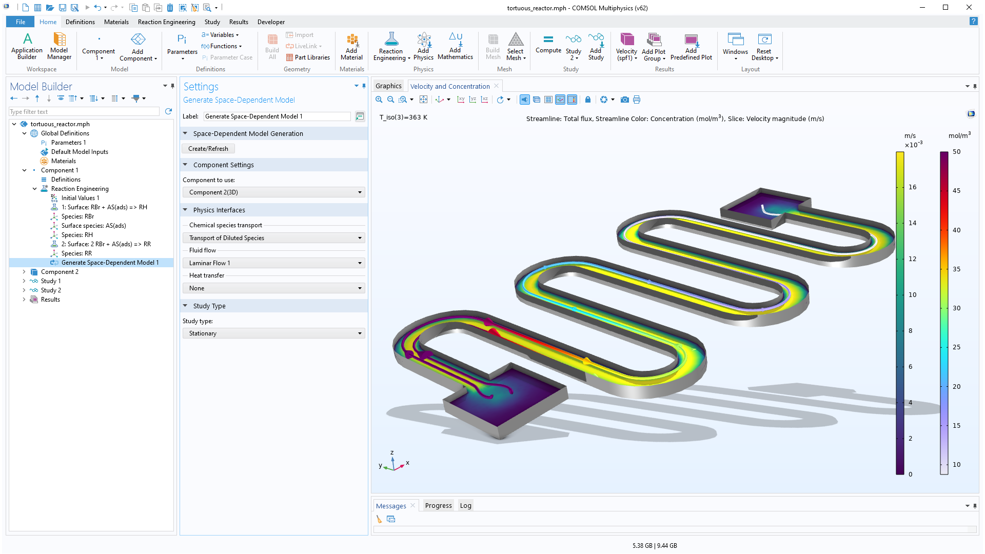
A working model for a perfectly mixed system can be used to automatically define material, energy, and momentum balances for space-dependent systems. The transport properties calculated in the Reaction Engineering interface (for example, heat capacity, thermal conductivity, viscosity, and binary diffusivity) automatically transfer to the physics interfaces for chemical species transport, heat transfer, and fluid flow. This functionality allows for refining kinetics and thermodynamics expressions of chemical reactions before moving to 2D, 2D axisymmetric, and 3D models.
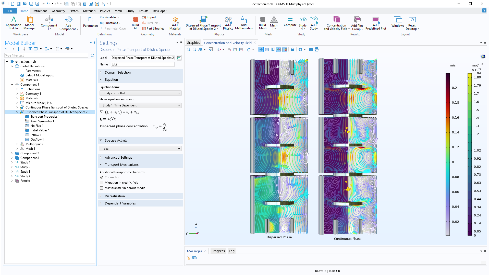
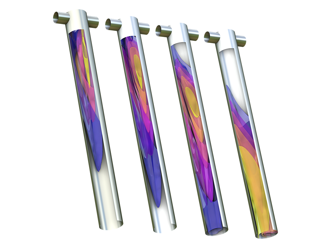
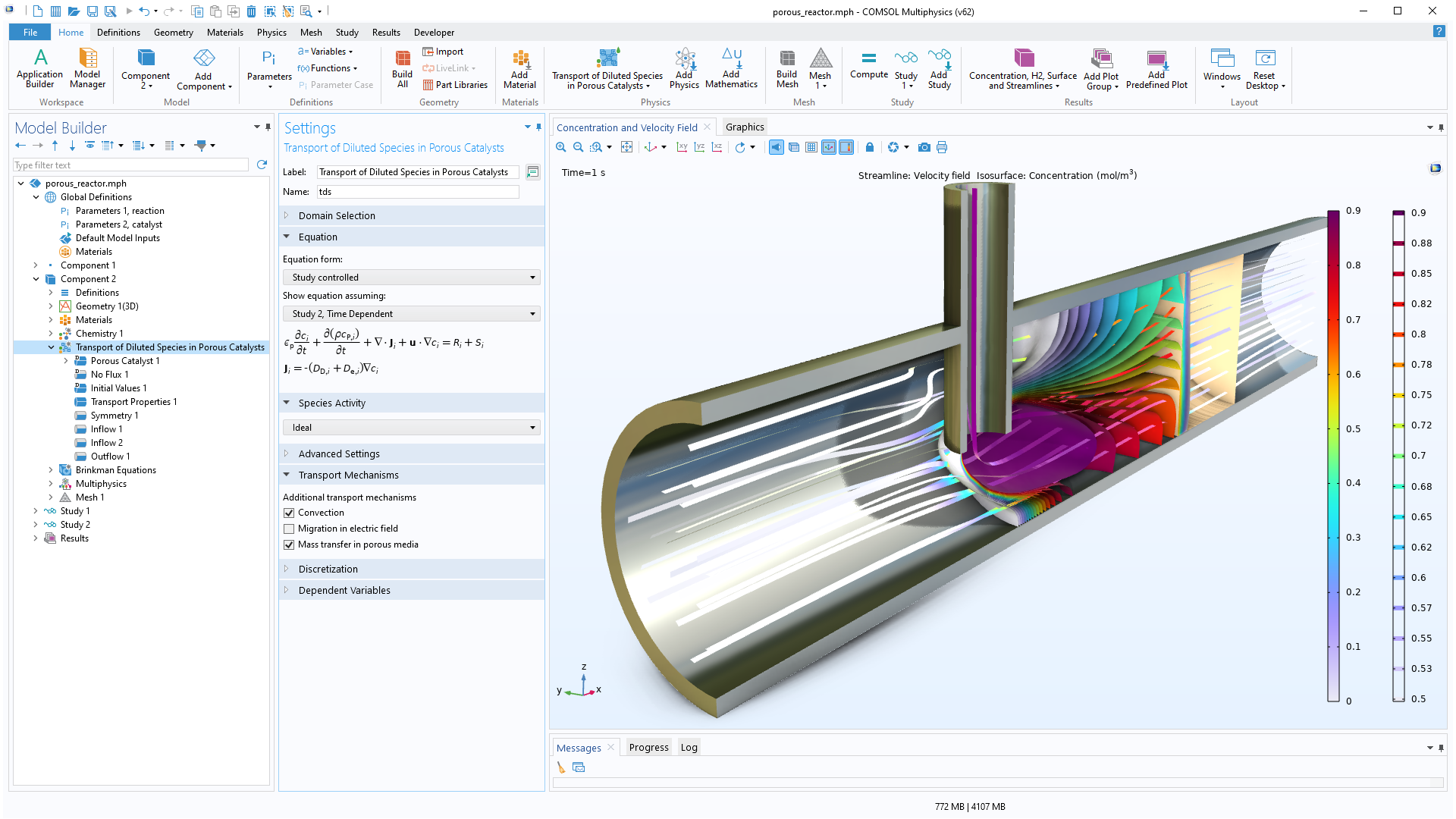
Modeling transport phenomena in reacting systems involves the description of the chemical species in so-called multicomponent transport models. The Chemical Reaction Engineering Module includes sophisticated models for multicomponent transport in the Transport of Concentrated Species interface, which offers the Maxwell–Stefan formulation and the mixture-averaged models for multicomponent transport. For diluted solutions, the Transport of Diluted Species interface is available, which treats cases where the interactions in the solution are dominated by solute–solvent interactions. The Dispersed Two-Phase Flow with Species Transport interface can be used to describe chemical species transfer between two immiscible fluid phases. The chemical species transport equations are also available for including Knudsen diffusion in, for example, porous media. The dusty gas diffusion model is also included. The formulation of the mass balance model as well as the transport properties can be obtained directly from chemical equations when generating a space-dependent model from the Reaction Engineering interface.
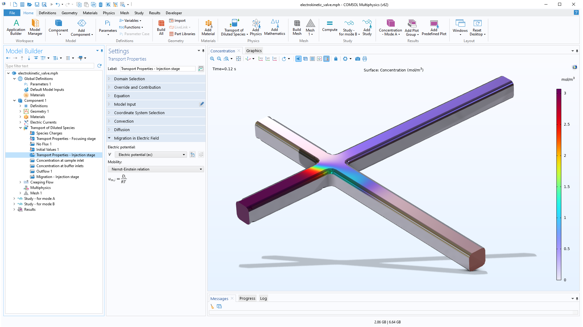
When modeling the transport of diluted or concentrated species, electric fields can be included as driving forces for transport for the modeling of electrolytes and ions. The Nernst-Planck and Electrophoretic Transport interfaces are dedicated to the modeling of electrolytes and can include the formulations of Poisson’s equation or the electroneutrality condition for the charge balance in the electrolyte. Applications of this functionality include electrokinetic valves, electroosmotic flow, and electrophoresis.
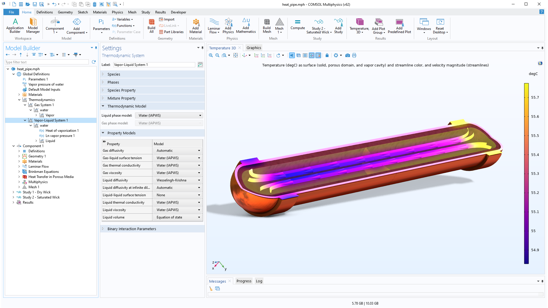
The Chemical Reaction Engineering Module contains a thermodynamic properties database, which can be used to calculate properties for gas mixtures, liquid mixtures, gas–liquid systems at equilibrium (flash calculations), liquid–liquid systems, and gas–liquid–liquid systems at equilibrium. There is a variety of thermodynamic models that can be used to calculate density, heat capacity, enthalpy of formation, enthalpy of reaction, viscosity, thermal conductivity, binary diffusivity, activity, and fugacity. Read more about this functionality on the Liquid & Gas Properties Module page, which is included in the Chemical Reaction Engineering Module.
The thermodynamic properties database can be used to create a so-called property package for a specific reacting system by selecting the chemical species present in the system, the desired properties, and the thermodynamic model. When defining reaction mechanisms, the reactants and products can be matched with the chemical species in the property package defined by the thermodynamic properties database. This matching automatically links the functions and equations generated by the property package to the model of the reacting system.
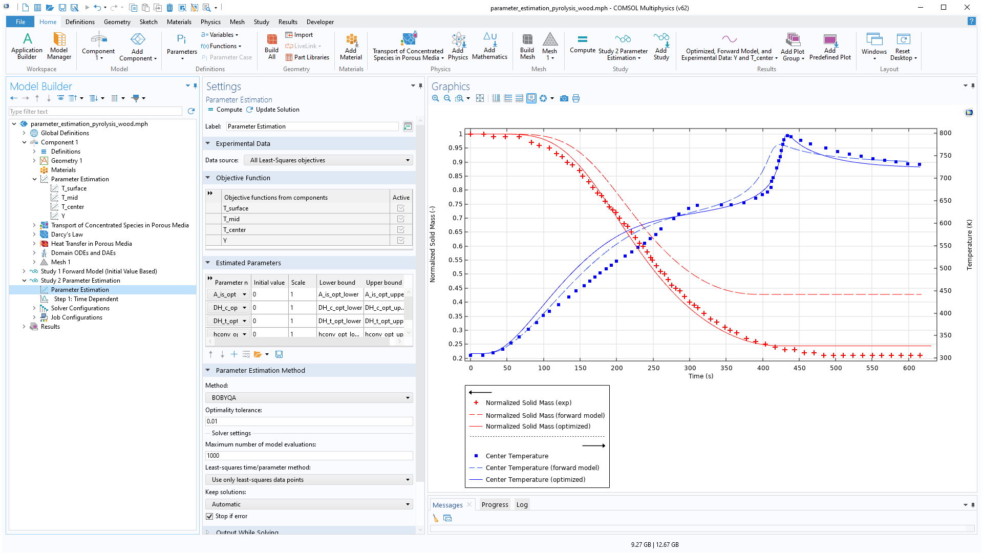
Analysis of systems of chemical reactions and reaction mechanisms usually rely on parameter estimation of frequency factors, activation energies, and other parameters that may quantitatively describe experimental observations. The Chemical Reaction Engineering Module includes dedicated features for parameter estimation, designed to optimize these parameters using data from multiple experiments.
The typical workflow for the estimation of model parameters is as follows: First, the model parameters to estimate (such as the rate constants) are selected, and the initial values and scales for the parameters are defined. Then, the experimental data is imported and data columns are correlated with model variables by entering the proper variable names or expressions.
Next, an optimization method is chosen and computed. The progress of the optimization can be inspected during computation. Once the optimal parameter values have been found, the results can be compared with experimental measurements.
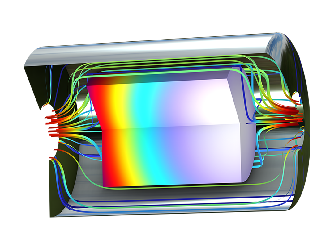
The fluid flow functionality included the Chemical Reaction Engineering Module can handle laminar and porous media flow. Additionally, when combined with the CFD Module, there are ready-made couplings for the modeling of chemical species transfer in turbulent flow. The formulation of the fluid flow model as well as the viscosity and density can be obtained directly from chemical equations when generating a space-dependent model from the Reaction Engineering interface.
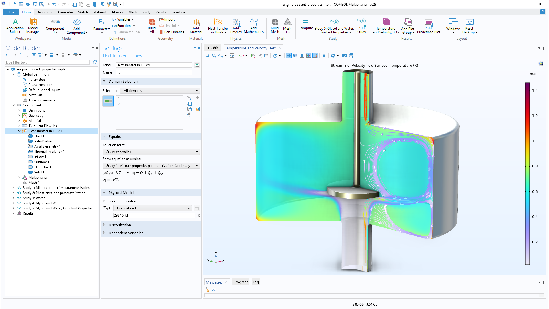
The heat transfer functionality included in the Chemical Reaction Engineering Module can account for heat transfer by conduction, convection, and radiation. The radiation term is given by surface-to-ambient radiation, while the Heat Transfer Module is required for surface-to-surface radiation and radiation in participating media. The heat transfer capabilities of the Chemical Reaction Engineering Module include heat transfer in fluids, solids, and porous media. The formulation of the heat transfer model, as well as the thermodynamic and transport properties, can be obtained directly from chemical equations when generating a space-dependent model from the Reaction Engineering interface.
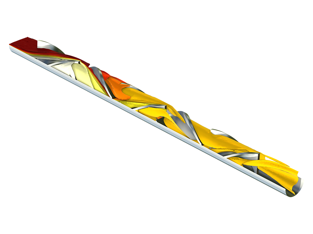
Surface reactions are typical for heterogeneous catalysis as well as for surface deposition processes such as chemical vapor deposition. They are found in the bulk chemicals industry, such as in the Haber–Bosch process for the production of ammonia and in microsensors for the detection of very low amounts of tracers that can adsorb on surfaces and be detected by, for example, a change in electrical properties.
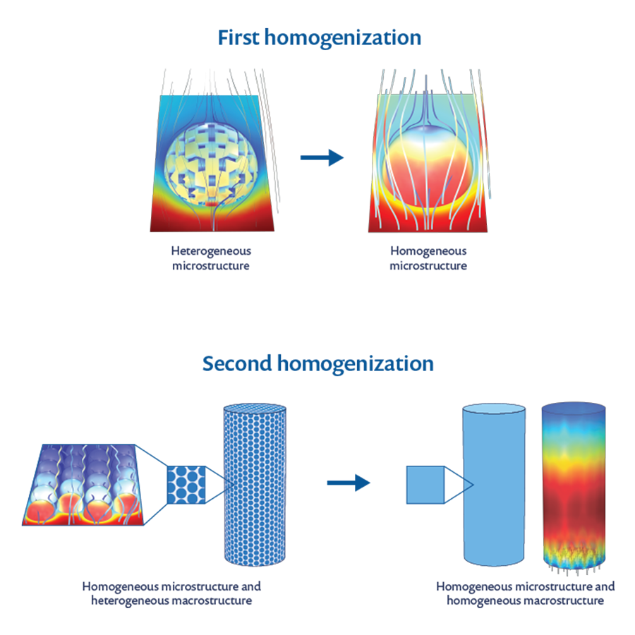
In transport-reaction models, surface reactions can be treated as boundary equations coupled to the boundary conditions for the transport and reaction equations in the bulk. This would be typical for models below or up to the microscopic scale. Alternatively, in porous media, these reactions are treated in a similar fashion as homogeneous reactions but include the specific surface area (area per unit volume of the porous material) and the effective transport properties. This would be typical for models both in the microscopic scale and the macroscopic scale — so-called multiscale models.
The Chemical Reaction Engineering Module includes ready-made formulations for heterogeneous catalysis for surface reactions on boundary faces as well as surface reactions distributed over a homogenized porous catalyst. For porous catalysts, multiscale models are predefined to describe bimodal pore structures. Such structures may consist of microporous pellets packed to form a macroporous pellet bed.
Every business and every simulation need is different.
In order to fully evaluate whether or not the COMSOL Multiphysics® software will meet your requirements, you need to contact us. By talking to one of our sales representatives, you will get personalized recommendations and fully documented examples to help you get the most out of your evaluation and guide you to choose the best license option to suit your needs.
Just click on the "Contact COMSOL" button, fill in your contact details and any specific comments or questions, and submit. You will receive a response from a sales representative within one business day.
Request a Software Demonstration