Battery Design Module

Understand, Design, and Optimize Battery Systems

Modeling batteries requires different levels of detail depending on the purpose of the simulations. The Battery Design Module is an add-on to the COMSOL Multiphysics® software that encompasses descriptions over a large range of scales, from the detailed structures in a battery's porous electrode to thermal management systems at the battery pack scale.

The descriptions involve physics phenomena such as transport of charged and neutral species, charge balances, chemical and electrochemical reactions, Joule heating and thermal effects due to electrochemical reactions, heat transfer, fluid flow, and other physical phenomena that are important for the understanding of a battery system.

Contact COMSOL
A battery pack model consisting of 200 batteries.

Lithium-Ion Batteries

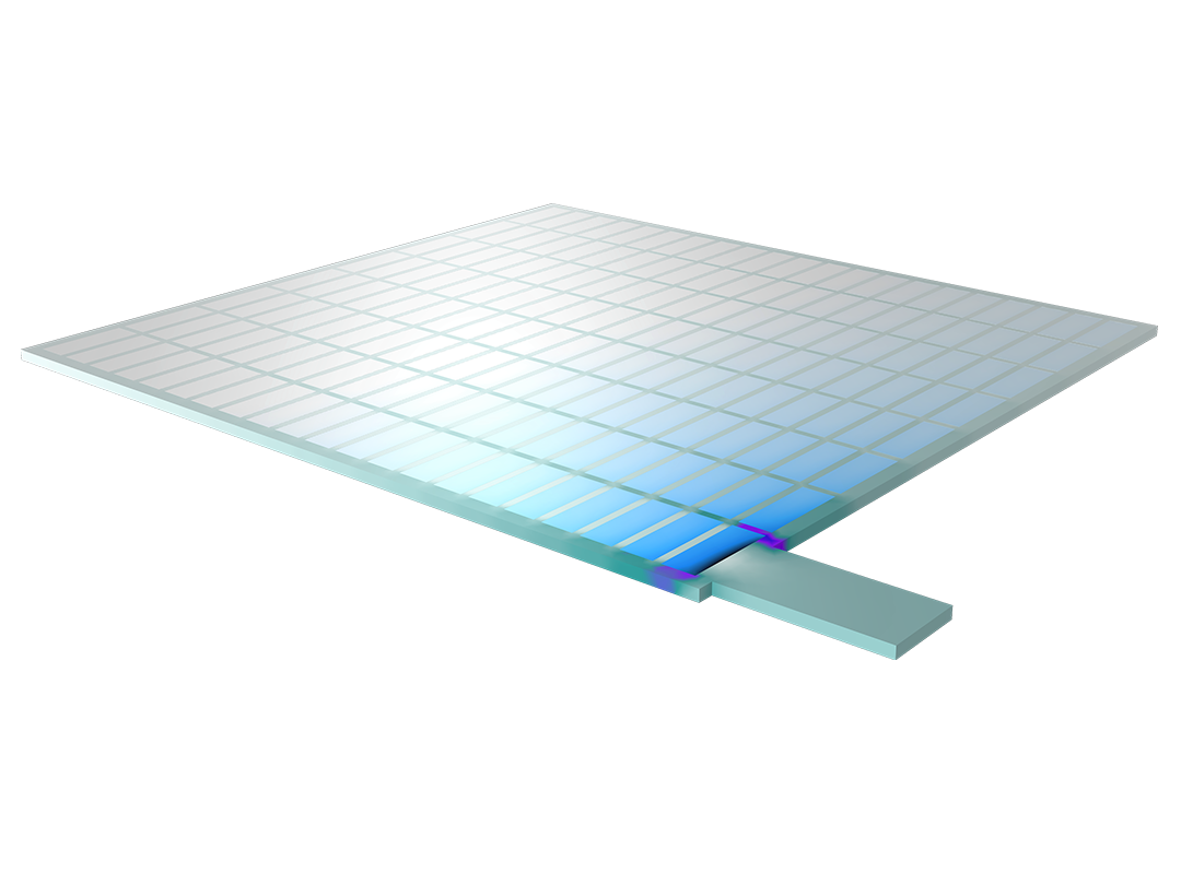
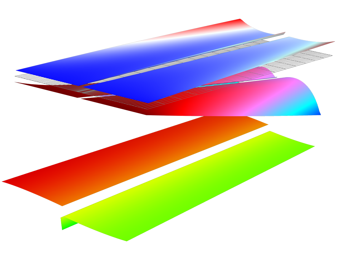
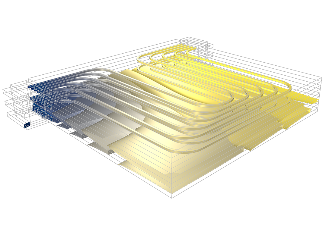
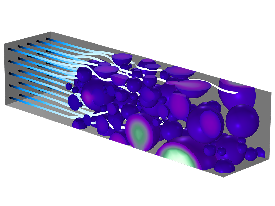
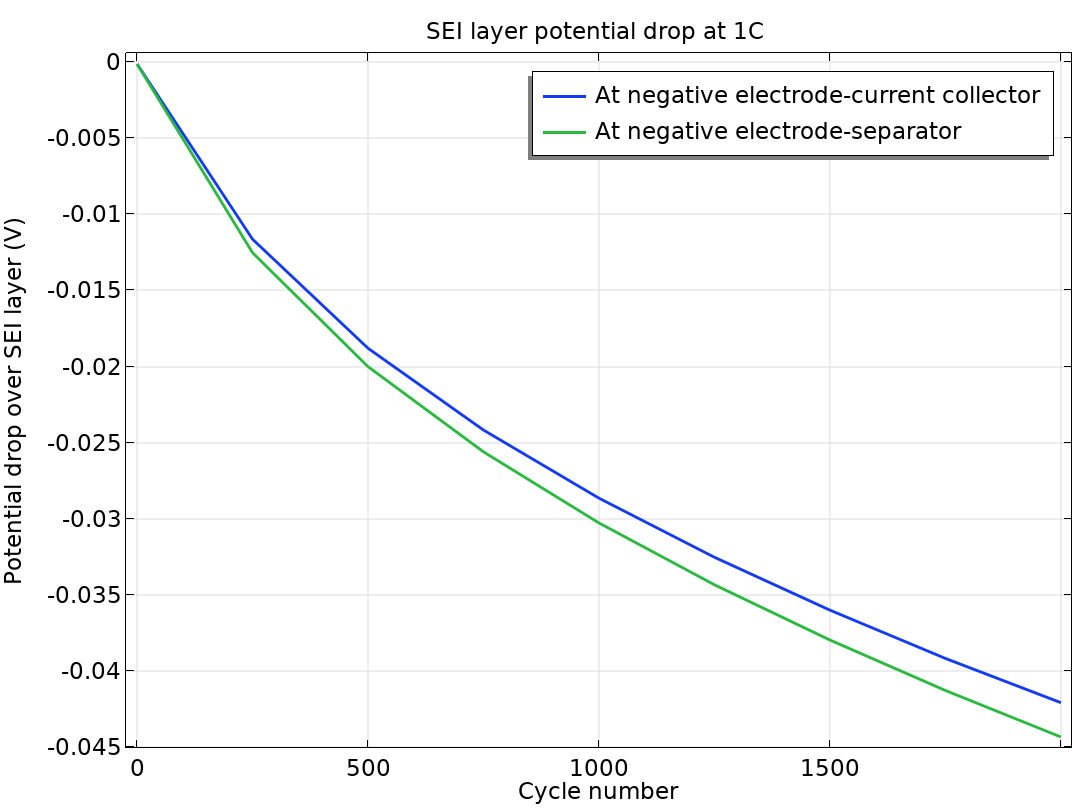
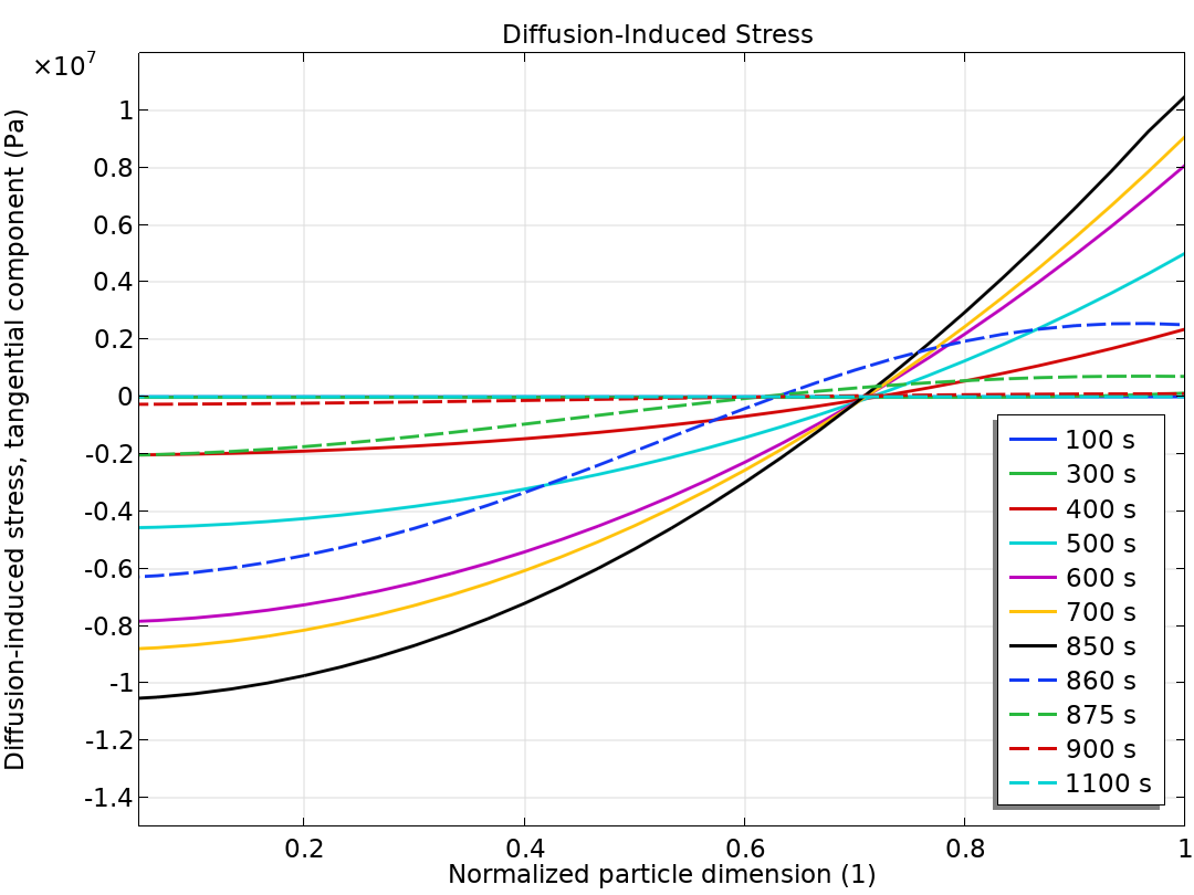
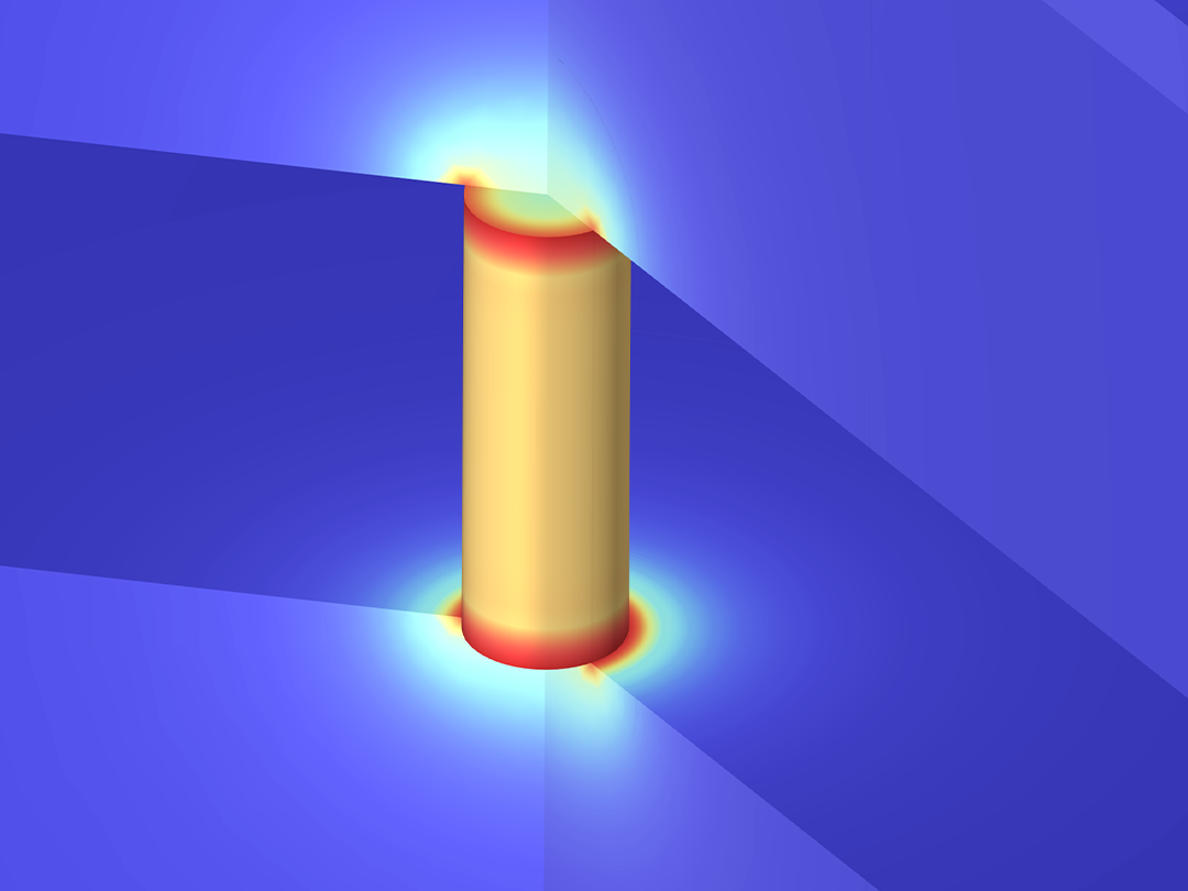
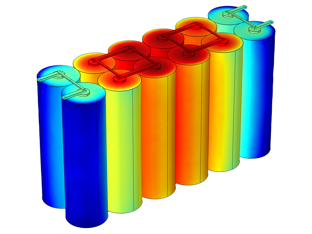
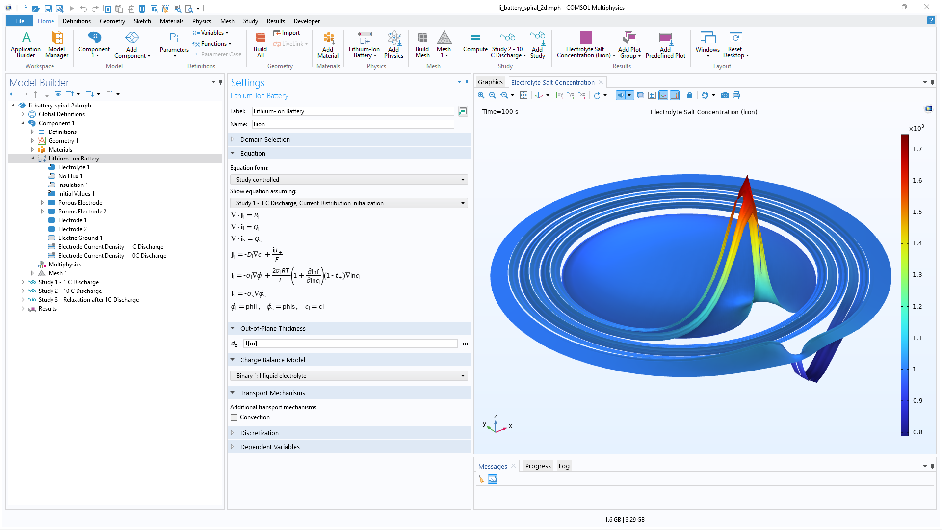
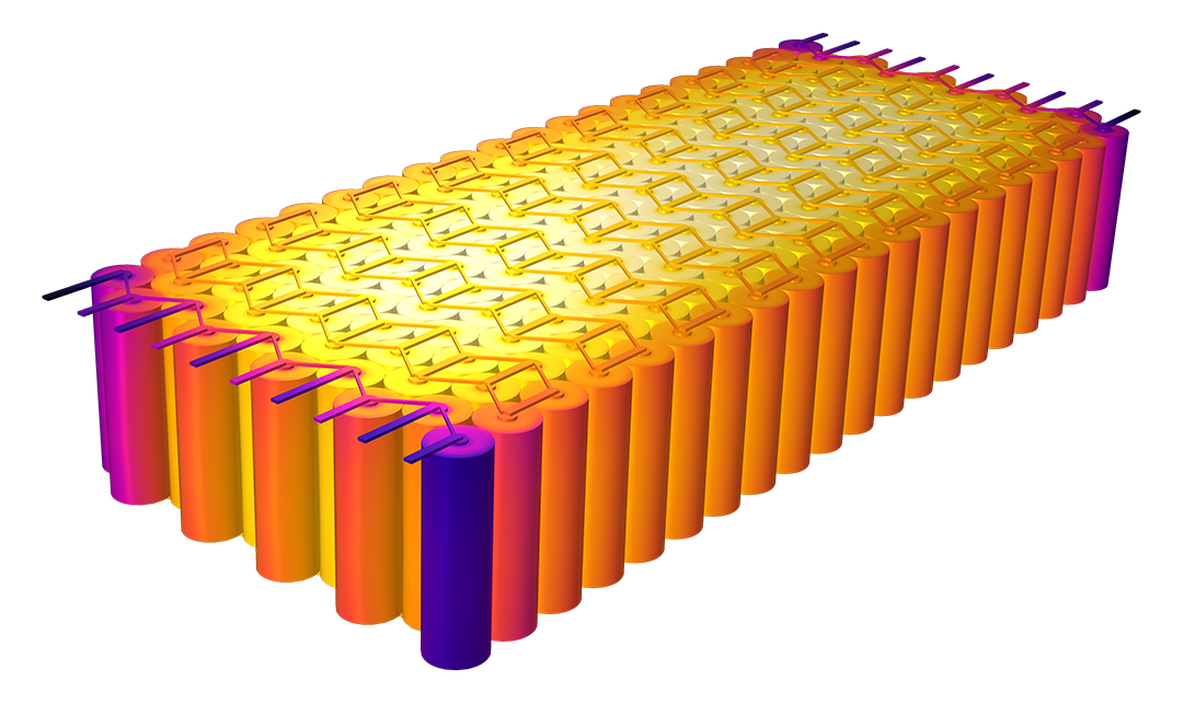
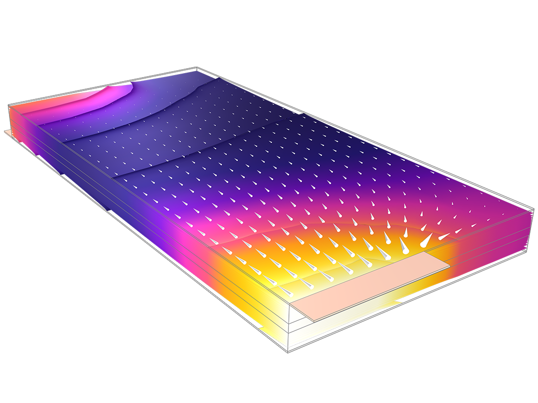
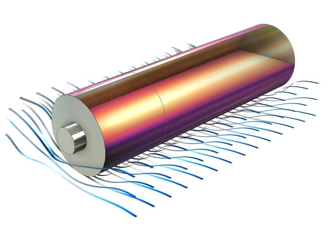
The Battery Design Module features state-of-the-art models for lithium-ion batteries. It includes different mechanisms for aging and high-fidelity models, such as the Newman model, available in 1D, 2D, and full 3D. In addition to modeling electrochemical reactions on their own, these reactions can be combined with heat transfer and account for the structural stresses and strains caused by the expansion and contraction from lithium intercalation. The module also provides functionality for setting up heterogenous models, which describe the actual shapes of the pore electrolyte and electrode particles. Studying the microstructure of a battery helps to provide a deeper understanding of the battery performance.

Lead–Acid Batteries

For the simulation of lead–acid batteries, the software includes dependent variables for the ionic potential and composition of an electrolyte and the electric potential and porosity in the solid electrodes. Models can also account for the dissolution and deposition of solids. Additionally, there are built-in features for studying how various design parameters affect the performance of a battery, such as the thickness and geometry of the electrodes and separators, as well as the geometry of the current collectors and feeders, among many other components.

Generic Batteries

The workhorse of the Battery Design Module is a detailed model of a battery unit cell with a positive electrode, negative electrode, and separator. With the generic description of porous electrodes, it is possible to define any number of competing reactions in an electrode and also couple this to an electrolyte of an arbitrary composition. The module makes it possible to describe the pore electrolyte and the electrolyte in the separator, for any composition, with the theory for concentrated, dilute (Nernst–Planck equations), and supporting electrolytes in combination with porous electrode theory.

What Can Be Modeled with the Battery Design Module

Perform various electrochemical analyses for batteries with the COMSOL® software.

A 3D model showing streamlines in a dark-blue-to-white color gradient that move through purple blob-like formations.

Heterogeneous and Homogenous Models

Model the detailed structure of the porous electrodes and the pore electrolyte for a representative unit cell of a battery.

A 1D plot showing the SEI layer potential drop at 1C with the potential drop over SEI layer on the y-axis and cycle number on the x-axis.

Growth of Solid-Electrolyte Interface (SEI)

Model aging in a negative graphite electrode of a lithium-ion battery.

A 1D plot of diffusion-induced stress with Pa on the y-axis and normalized particle dimension on the x-axis.

Diffusion-Induced Stress

Compute intercalation stresses and strains caused by expansion and contraction.

A zoomed-in view of a model with a cylinder shown in yellow surrounded by a Heat Camera color gradient.

Short-Circuiting

Investigate an internal short circuit of a battery.

A battery pack model of 12 cylindrical batteries with temperature shown in rainbow.

Pseudo-Dimension

Model the intercalation of lithium in the electrode particles.

A 1D plot of the concentration profiles of a diffuse double-layer model.

Double-Layer Capacitance

Model electrochemical capacitors and nanoelectrodes.

A 1D plot showing discharge rates.

Ni-MH and NiCd Batteries

Model batteries with alkaline binary (1:1) electrolytes, including nickel–metal hydride (Ni–MH) and nickel–cadmium (NiCd) batteries.

Lead flow visualized in rainbow.

Flow Batteries

Simulate lead–acid and vanadium flow batteries during an applied charge–discharge load cycle.

A 1D plot showing relative capacity loss.

Metal Plating

Specify electrode host capacities to avoid lithium metal plating during high-rate charging.

A 1D plot with porosity on the y-axis and dimensionless thickness of positive electrode on the x-axis.

Porosity Effects

Model chemical reactions influenced by species transport in porous media.

A 1D plot showing simulated impedance NCA vs. reference in blue and experimental impedance NCA vs. reference in green, where the two lines are closely matched until 0.0016.

Impedance Spectroscopy

Study the harmonic response of a battery using physics-based high-fidelity models.

A 1D plot with cell potential in volt on the y-axis and time in seconds on the x-axis, and lines for the modeled cell voltage in blue and experimental cell voltage in green; the two lines are a close match.

Lumped Models with Parameter Estimation

Define a simplified battery model based on a small set of lumped parameters that fit results from high-fidelity models to experimental results.

A close-up view of a battery pack model showing the temperature.

Thermal Runaway

Simulate thermal runaway propagation in a battery module or pack using event-based heat sources.

Features and Functionality in the Battery Design Module

The Battery Design Module offers a set of specialized features for simulating the performance of batteries under different operating conditions.

A close-up view of the Model Builder with the Voltage-Losses node highlighted and a model showing the temperature of a battery pack in the Graphics window.

Battery Pack Modeling

For faster thermal analysis of 3D battery packs, validated lumped (simplified) models can be used for each battery in a pack. Once validated, the lumped models may give excellent accuracy within a particular range of operation. The Battery Design Module contains lumped models that are physics-based and solve the electrochemical equations in multiple space dimensions.

The Single Particle Battery interface models the charge distribution in a battery using one separate single-particle model each for the positive and negative electrodes of the battery. The Lumped Battery interface makes use of a small set of lumped parameters for adding contributions for the sum of all voltage losses in the battery, stemming from ohmic resistances and, optionally, charge transfer and diffusion processes. For setting up multiple lumped battery models and connecting them in a 3D geometry, a Battery Pack interface is available for modeling thermal pack management. This interface is typically used together with a Heat Transfer interface, and it features thermal events that can be used to study thermal runaway propagation problems. Additionally, a battery model based on an arbitrary number of electrical circuit elements can be defined with the Battery Equivalent Circuit interface.

A close-up view of the Porous Electrode Reaction settings and the electrolyte concentration plot of a lead–acid battery in the Graphics window.

Porous Electrodes with an Arbitrary Number of Electrochemical Reactions

Battery systems and chemistries are often burdened by unwanted side reactions at the electrodes, and the impact of these reactions on charge and discharge cycles, as well as on self-discharge, can be investigated. There is a database for predefined reactions, but arbitrary by-reactions can be added to an electrode.

Typical by-reactions that can be modeled include hydrogen evolution, oxygen evolution, the growth of a solid–electrolyte interface, metal plating, metal corrosion, and graphite oxidation.

The COMSOL Multiphysics UI showing the Model Builder with the Frequency-Domain Perturbation node highlighted, the corresponding Settings window, and a 1D plot of the impedance for the model.

Fully Transient and Impedance Spectroscopy Studies

Battery systems are often closed systems that are difficult to study during operation. Transient methods such as potential step, current interrupt, and impedance spectroscopy can be used to characterize a battery during operation.

Transient studies make it possible to perform parameter estimation at different time scales and frequencies to separate ohmic, kinetics, transport, and other losses that may be responsible for battery aging. Using transient techniques, modeling, and parameter estimation enables very accurate estimations of the state of health of a battery system.

A close-up view of the Model Builder with the Lithium-Ion Battery node highlighted and a spiral battery model in the Graphics window.

High-Fidelity Battery Modeling

The Lithium-Ion Battery interface is used to compute the potential and current distributions in a lithium-ion battery. Multiple intercalating electrode materials can be used, and voltage losses due to solid–electrolyte interface (SEI) layers are also included.

The Battery with Binary Electrolyte interface is used to compute the potential and current distributions in a generic battery. Multiple intercalating electrode materials can be used, and voltage losses due to film formation on the porous electrodes can also be included.

A close-up view of the Particle Intercalation settings and a plot of the voltage profiles of a lithium-ion battery in the Graphics window.

Intercalating Species and Transport in Pore Structures

The particles in porous battery electrodes can either be solid (Li-ion electrode) or porous (lead–acid, NiCd). In the case of solid particles, the porosity in the electrode is found between the packed particles. However, transport and reactions may occur in the solid particles for small atoms such as hydrogen and lithium atoms. These intercalating species are modeled with a separate diffusion-reaction equation defined along the radius of the solid particles. The flux of the intercalating species is coupled at the surface of the particles with the species that are transported in the pore electrolyte between the particles. The intercalation species and reactions are predefined for Li-ion batteries, but the same functionality can be used to model intercalation of hydrogen in, for example, Ni–MH batteries.

In the case of porous particles, a bimodal pore structure is obtained: a macroporous structure between the packed particles and a microporous structure inside the particles. The reaction–diffusion equations in the porous particles are defined in a similar fashion as for the intercalation of species in solid particles.

A close-up view of the Add Material options and the temperature of a jelly roll model in the Graphics window.

Built-In Thermodynamics and Material Properties

The battery material database included in the module contains entries for a number of common electrodes and electrolytes, substantially reducing the amount of work needed for creating new battery models.

One of the more time-consuming and error-prone steps in the modeling of battery systems is to gather input data that then needs to be used consistently. For example, it is important that the positive and negative electrodes are defined in the same reference systems. The equilibrium electrode (half-cell) potentials have to be measured or calibrated to the same reference electrodes, electrolytes, and temperatures before they are incorporated in the same battery system model.

Every business and every simulation need is different.

In order to fully evaluate whether or not the COMSOL Multiphysics® software will meet your requirements, you need to contact us. By talking to one of our sales representatives, you will get personalized recommendations and fully documented examples to help you get the most out of your evaluation and guide you to choose the best license option to suit your needs.

Just click on the "Contact COMSOL" button, fill in your contact details and any specific comments or questions, and submit. You will receive a response from a sales representative within one business day.

Next Step

Request a Software Demonstration