A couple of weeks ago, I led a webinar on postprocessing and visualization features in COMSOL Multiphysics. This webinar was very popular among COMSOL users, so I wanted to follow up with a blog post to highlight one of the important topics we covered — performing a mesh refinement study in COMSOL Multiphysics.
Editor’s note: This blog post was updated on 12/19/2016 to reflect new terminology used in COMSOL Multiphysics.
Best Mesh Size and Fineness for a Mesh Refinement Study
COMSOL primarily uses the finite element method (FEM) to compute single- and multiphysics simulations. Whenever you use the finite element method, it is important to remember that the accuracy of your solution is linked to the mesh size. As mesh size decreases towards zero (leading to a model of infinite size), you move toward the exact solution for the equations you are solving. However, since we are limited by finite computational resources and time, you will have to rely on an approximation of the real solution. The goal of simulation, therefore, is to minimize the difference (“error”) between the exact and the approximated solution, and to ensure that the error is below some accepted tolerance level that will vary from project to project based on your design and analysis goals.
You will need to track a characteristic output parameter from your simulation as you vary the mesh size and determine at which mesh size the parameter has “converged” on the correct value. Note that “converged” is used in quotation marks because the convergence criteria will depend on your design and analysis goals.
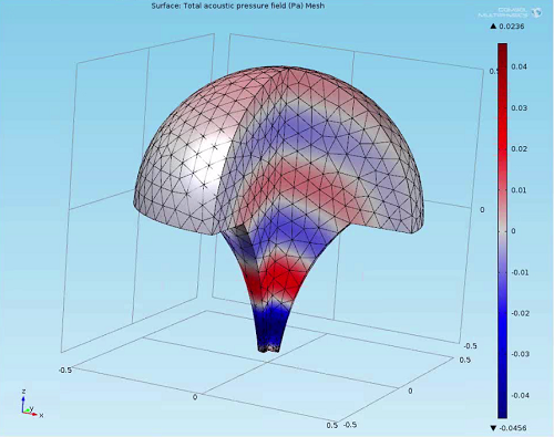
You can read the step-by-step instructions below to learn how to perform a mesh refinement study. You can also watch the archived Postprocessing and Visualization webinar below to see how the steps are carried out on a megaphone geometry.
Archived Webinar: Postprocessing and Visualization
Implementing a Mesh Refinement Study
In order to implement a mesh refinement study in COMSOL Multiphysics, you must first decide what output parameter you will use for your convergence criteria. This must be a numerical value evaluated over some, or all, of the nodes in your mesh. You can track a variable or mathematical expression of variables at a single point of interest, or you can use some operation (integral, average, minimum, maximum, etc.) performed over one or more domains, boundaries, or edges. If you choose the latter option, you can define the integral, average, minimum, or maximum operator by right-clicking Component 1 > Definitions and choosing the appropriate option in the Component Couplings menu, then selecting which geometric entity or entities to apply the operation to. Note that this should be added to your model before running your simulation. This should take care of setting up your output parameter.
Now you need to set up your mesh size by applying a user-defined parameter. Define a parameter under Global Definitions > Parameters and then use that parameter in the relevant Size feature in the Mesh node of your model to define a maximum element size.
Next, right-click your Study node and add a Parametric Sweep. In the Settings window, add your dummy mesh size parameter to the Parameter names list and enter the range of values to sweep your parameter over. Be sure you sweep through a wide enough range of maximum mesh sizes so you can fully capture the convergence effect in your analysis. This range will depend on your geometry and the nature of the physics equations you are solving. For example, for wave radiation problems, we recommend you use at least 5 elements per wavelength for a 3D problem and at least 8 elements per wavelength for a 2D problem, but you may still need to verify the best mesh size for your model using a mesh refinement study.
After computing the simulation, you will need to first set up a Join data set that compares the tracking parameter at each mesh size with the value of the tracking parameter that is considered to be the reliable solution; the solution at our finest mesh size will be chosen as that reliable solution here. Right-click Results > Data Sets and choose Join. Then in the Settings window, choose the solution containing your parametric sweep results (usually Solution 2) and select All solutions for Data 1, and click on the solution you want to compare your Parametric Sweep results to for Data 2 (Data: Solution 2, Solutions: One, etc.). Since we want to subtract these values, keep the Combination method as the default Difference option.
Once you’ve completed all of these steps, you are ready to create your plot. Add a 1D Plot Group with a Global or Point plot (depending on which parameter you are tracking for your convergence criteria, as described above), and make sure you specify the Data set as Join 1. Then type in the expression for the tracking parameter you are monitoring the convergence of and from the x-Axis Data > Axis source data drop-down menu, choose Outer solutions if you are running a Frequency Domain simulation (because your frequency range is considered your inner solution). Finally, click the Plot icon above the Settings window and you will see your convergence plot.
You can download the megaphone model file used in the Postprocessing and Visualization webinar below, which includes the completed mesh refinement study I demonstrated.
Below are a couple of key things that you’ll notice in the final model:
- The parameter elements_per_wavelength is used in the Parametric sweep to sweep from 1 element per wavelength through 8 elements per wavelength (remember, the recommended value is 5 for this wave radiation problem), but the maximum mesh size is defined by the parameter max_element_size, which is the wavelength divided by the elements_per_wavelength parameter.
- We are tracking the convergence of the maximum sound pressure level (SPL) in this model, so we first define the maximum operator on the domain of interest under Component 1 > Definitions > Maximum 1 and then after running the simulation we plot the expression maxop1(acpr.Lp) in a 1D Global plot. Note that operators act as functions, and you can find their “function” name listed in italics next to the operator in the Model Builder window. Here we are finding the maximum of the variable acpr.Lp, which is the sound pressure level (SPL), so acpr.Lp is the argument in parentheses.

Mesh Refinement Study in the process of being implemented in an acoustic megaphone geometry
Additional Resources
- Download the final megaphone model file that was used in the webinar
- Explore the videos on postprocessing in our Video Center
- Read the “Results Analysis and Plots” chapter (Chapter 20) in the COMSOL Reference Manual, downloadable from your COMSOL Access account
- Download the original megaphone model file from the knowledge database entry, Frequency-Dependent Meshing


Comments (4)
Johan Bergström
November 16, 2017Don’t you run the risk of running out of memory if you try to sweep over fine meshes for a large geometry while using this method?
Do you have to run each refinement separately to make that work?
Caty Fairclough
December 6, 2017Hi Johan,
Thanks for your comment! Using a fine mesh may lead to running out of memory, but the method suggested by the presenters will not require more memory than any other method to study the effect of the mesh size.
The general question of how much memory is needed for solving large models is discussed in this blog post:
https://www.comsol.com/blogs/much-memory-needed-solve-large-comsol-models/
Muhammad Gulzari
March 5, 2018Dear Bethany Nine,
Very informative. What If I am doing solid mechanics, eigenfrequency analysis. My structure is small as compare to wavelength. I tried to adopt your method but no good convergence I achieve.
Thank you
Caty Fairclough
March 9, 2018Hi Muhammad,
Thanks for your comment.
For your question, please contact our Support team.
Online Support Center: https://www.comsol.com/support
Email: support@comsol.com