

During the design phase of microwave heating solutions for prepackaged foods, wireless sensors may be integrated to evaluate the temperature and pressure inside of the packaging in real time, ensuring long-term microbiological safety and limiting postprocess recontamination. While this approach is a reliable alternative to traditional retort processing (where packaged food is sterilized inside hermetically sealed containers), the geometry and placement of the sensor may influence the electromagnetic power dissipation within the microwave cavity.
Building the COMSOL® Model
To get a better idea of the interference these sensors may introduce, a collaborative team from GEPEA–Oniris (Process Engineering–Environment–Agri–Food Joint Research Unit, National College of Veterinary Medicine, Food Science and Engineering, Nantes, France) and CTCPA (agri-food technical center in France) ran a study that evaluated these in-package microwave heating processes by simulating the effects of different sensor positions within a single-mode microwave applicator. The study focused on a lab-scale 915-MHz microwave heating process for 300 g of mashed potato in a polypropylene tray. The 3D model geometry of the microwave equipment was built in the COMSOL Multiphysics® software, while the experimentally measured geometry of the polypropylene tray was imported to COMSOL® from a custom-made STL file.
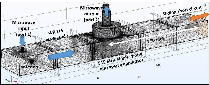 Figure 1. Description of the 915-MHz single-mode microwave apparatus.
The model the team built was robust, taking into account all of the geometrical details of the microwave apparatus. It included the complete design of a waveguide transition, an impedance matching element (i.e., an iris), a 915-MHz single-mode microwave applicator, and a sliding short circuit. The microwave input power source was modeled with a coaxial port at the microwave antenna. All surfaces of the waveguide, including the copper sliding short circuit, were considered as perfect electric conductors. The dielectric properties of the mashed potato were experimentally measured and assumed to correspond to a constant moisture content of 76% on a wet basis.
To avoid microwave interference with metallic parts, the wireless sensor was surrounded by an ogive-shaped 316-L stainless steel microwave shield and placed at the upper surface of the mashed potato sample. Additionally, a polypropylene film was heat-sealed at the top surface of the polypropylene tray to close the system. Each of these components came together to create a numerical model that helped the team derive accurate insights into the best in-package sensor position to limit interactions with the electromagnetic field.
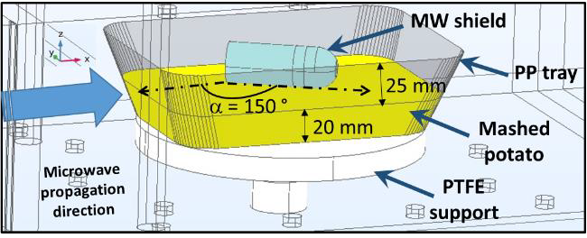 Figure 2. Description of the polypropylene tray filled with a mashed potato sample. MW = microwave, PP = polypropylene, and PTFE = polytetrafluoroethylene.
Simulation-Based Insights
The team used the RF Module, an add-on to COMSOL Multiphysics®, to predict the electromagnetic field in the microwave cavity relative to the microwave-absorbed power within the sample of mashed potato. For the solver settings, boundary mode analysis was used as a first step to compute the mode at port 2 (see Figure 1), which comes out of the waveguide. The second step was using a Frequency-Stationary study at 915 MHz.
Without a sensor inside the tray, the simulation revealed microwave-reflected power of 24% (S11 = -6.16 dB), with the optimal sliding short circuit position at 790 mm. S11, the input port reflection coefficient (i.e., the measure of the port’s mismatch), was then evaluated as a function of varying microwave shield positions following different z-axis rotations, from alpha = 0 to 180°, with 30° increments.
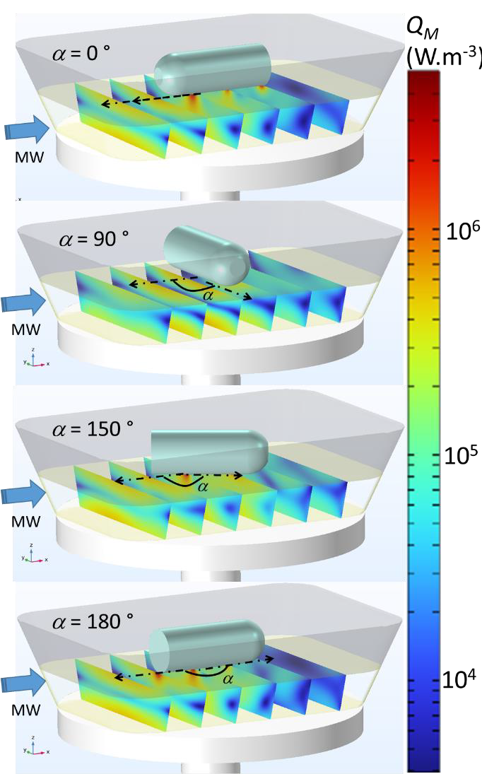 Figure 3. Local microwave-absorbed power within the mashed potato as a function of four sensor positions.
The results showed that the microwave shield position needed to be aligned to the microwave propagation direction (alpha = 0°) to obtain a similar S11 parameter to the food tray without the sensor (S11 ≈ -6 dB, RF ≈ 25%). When rotated counterclockwise by 90°, so the microwave shield position faced the same direction as the transverse electric plane, the S11 parameter dropped to -7.8 dB. Furthermore, by changing the rotation angle of the microwave shield from 90 to 180°, simulation results indicated S11 variations from -7.8 to -4.7 dB. This rotation from 90 to 180° also resulted in the simulated microwave reflected power increasing by a factor of 2, with 17% microwave reflected power at 90° and 33% at the 180° rotation. These results suggest that the sensor positioning is crucial to take into account, as these reflected power variations can impact overall microwave power efficiency.
A portable vector network analyzer (VNA) was used in the experimental validation of the numerical model. The VNA was connected at port 1 to evaluate the microwave-reflected power from the load according to different operating conditions. The S11 parameter was used to account for the microwave-reflected power at the antenna relative to the incident microwave power. Overall, the simulation results were in agreement with the experimental measurements performed with the VNA. Discrepancies between the experimental and simulation results can be attributed to slight variations in sensor positioning due to the difficulty of precisely replicating the uneven surface of the mashed potato.
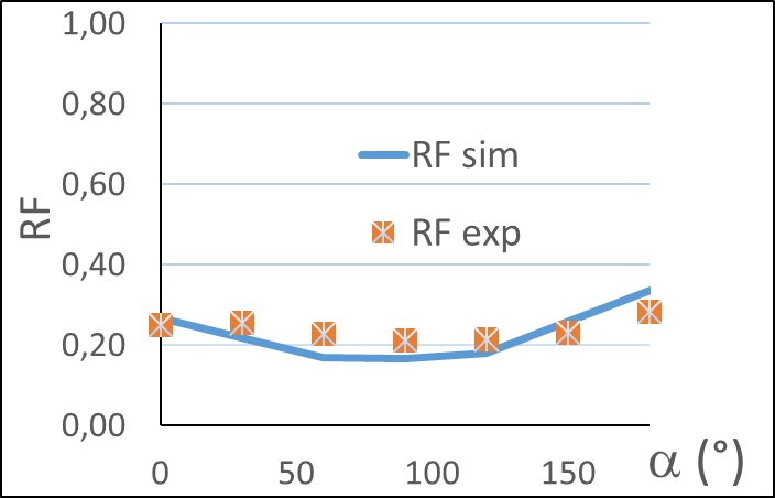 Figure 4. Reflection factor following different rotation angles of the microwave shield.
An Important Discovery
This study led to an important discovery: Aligning the sensor position with the microwave propagation direction resulted in a similar microwave reflection coefficient as tests run without a sensor. However, a significant reduction of the microwave-reflected power is observed if the microwave shield is positioned within the transverse electric plane of the waveguide.
Testing showed that the model is also able to predict the high local microwave power densities at the interface between the sensor and the food sample, which could further elucidate the best position for a temperature and pressure (T-and-P) sensor, though this would require more experimental validation and accounting for potential temperature-dependent dielectric properties of the food, as well as their coupled impact on the electric field distribution.
Further Learning
For more information on this research, read the GEPEA-Oniris and CTCPA team’s full paper, which won a Best Paper award at the COMSOL Conference 2025 Amsterdam! The paper describes the team’s full modeling approach and results.





Comments (0)