
Slope stability analysis is essential for ensuring the reliability of dam embankments and safety of people in their proximity. By using a shear strength reduction method in the COMSOL Multiphysics® software, civil and geotechnical engineers can evaluate the stability of dam embankments to predict failure and prevent tragedy.
Why Analyze Dam Failure?
When a dam fails, the results can be devastating — even fatal. For instance, the Austin Dam, built in the late 1800s near Austin, Texas, was both expensive and difficult to construct. However, many citizens believed that the dam would attract business and supply power to the city. On April 7, 1900, heavy rainfall and flooding from the previous week caused the lake behind the dam to swell. The dam could not resist the force of the water, and it eventually cracked. Sections of the dam caved, releasing torrents of water and causing fatalities and severe damage to over 500 homes.
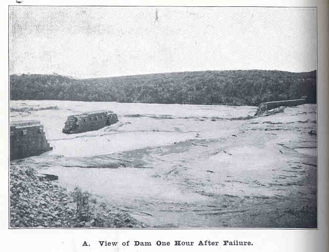
The damage resulting from the Austin dam failure one hour after collapse. Image in the public domain, via Wikimedia Commons.
In the aftermath of what would be known as the “Great Granite Dam Failure”, the structural integrity of the dam was called into question. People surmised that the collapse of the dam was inevitable due to its suboptimal design and construction.
However, accounting for the stability and reliability of a dam can begin long before it is even built. Slope stability analysis, for instance, can be used to predict the settlement, deformation, and slippage of soil in a dam embankment due to various loading and environmental conditions.
There are numerous methods for conducting a slope stability analysis. Here, we discuss a technique for modeling this process with COMSOL Multiphysics and the add-on Geomechanics Module, using the Slope Stability in a Dam Embankment tutorial model from the Application Gallery.
Shear Strength Reduction and Factor of Safety
Stability refers to the ability of a slope to resist forces that drive Earth’s materials down the slope. The shear strength reduction (SSR) method is used to find the safety factor value of the slope at the point of failure, or the instability point.
In the model discussed here, we conduct a slope stability analysis of a dam embankment using the SSR method. This model also uses a plane strain approximation to model the dam embankment in 2D, which is more computationally efficient than a 3D analysis.
The factor of safety (FOS) is defined as the ratio of the available shear strength of the soil that is required to maintain an equilibrium across the surface. The FOS ratio demonstrates how much a structure (the dam, in this case) can withstand. In the context of slope stability, the FOS would ideally be a ratio that does not lead to sliding of the materials in the slope (the dam embankment, in this case).
FOS is not a measure on the reliability of the embankment, but rather a relative indication of the resistance to any driving force within the slope stability analysis. If the FOS equals 1, the structure or part supports the exact stress it would be subjected to, and increasing or subjecting the part to any higher stress (or load) will result in the structure failing. For an FOS value of 2, the structure or part will fail at twice the working stress. If the FOS is less than 1, it means that the structure is unstable.
Think of building a sand castle at the beach when you were a child. If you formed a pile of sand and then slowly placed your hand on it at an angle, the compression of the sand underneath your hand at a certain force would cause the sand to “slip” and translate toward the base of the slope. Now, picture digging a moat in the sand around a sand castle: If you dug deeper and deeper into the sand, the moat would eventually collapse due to the reduced strength of the slope.
Slope soil behavior is represented by the following elements:
- Darcy’s law:
- Pore pressure
- Flow of fluid through a porous medium
- Mohr–Coulomb criterion:
- Elastoplastic analysis
Including Darcy’s law for the soil accounts for the pressure head in the embankment and also makes it possible to distinguish between saturated or unsaturated conditions. Then, by adding the Mohr–Coulomb criterion in the Solid Mechanics interface, you can determine the stability of the slope.
Mohr–Coulomb Criterion
The Mohr–Coulomb theory is a mathematical model that describes how materials — brittle materials specifically — respond to shear stress and normal stress. The Mohr–Coulomb criterion is a common failure criterion in geotechnical engineering, and it demonstrates the linear relationship between normal and shear stresses at the point of failure.
In the SSR method, the Mohr–Coulomb material parameters are functions of the FOS. With the SSR technique, the FOS affects the cohesion as well as the angle of internal friction.
Cohesion describes how strongly a material will stick together. Think of packing sand into a mold for your sand castle. If the sand is wet or damp, it’s less likely to fall apart when the mold is flipped over.
The angle of internal friction describes the frictional shear resistance of the soil. If you pour sand into one specific spot on a surface, the sand accumulates, but if you attempt the same task with a different item, such as marbles, it doesn’t have the same result. Sand collects into a pile due to its higher angle of internal friction (right video), but marbles are perfectly round and will slip past one another to reach the surface onto which you are pouring them (left video).
Under the Mohr–Coulomb criterion, these factors specify the shear strength of the soil and can predict the likelihood of a dam embankment’s slope to slip or hold itself together.
Interpreting the Simulation Results
To find the point at which the dam embankment reaches instability, we can systematically run the model for increasing FOS values until it fails to converge. This point indicates when the slope is no longer stable; that is, we’ve identified its expected FOS.
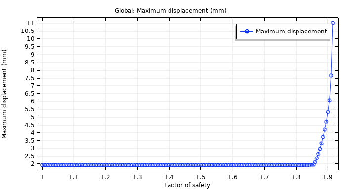
A graph of the maximum displacement versus the factor of safety for the dam embankment.


Left: Pressure head in the dam embankment. Middle: Effective plastic strain prior to collapse. Right: Slip circle just before collapse.
Here, the elastoplastic analysis does not converge for FOS values over 1.915. As mentioned, the lowest value accepted for the FOS is 1, and a 2 would indicate that the structure fails at twice the working stress. With an FOS of 1.915, the available shear strength of the soil is almost twice what is needed to sustain the slope. At this point, the slope would collapse due to increased strain and a subsequent reduction of the shear strength. This collapse is caused by the localization of plastic strains into a shear band, which results in the formation of a slip circle.
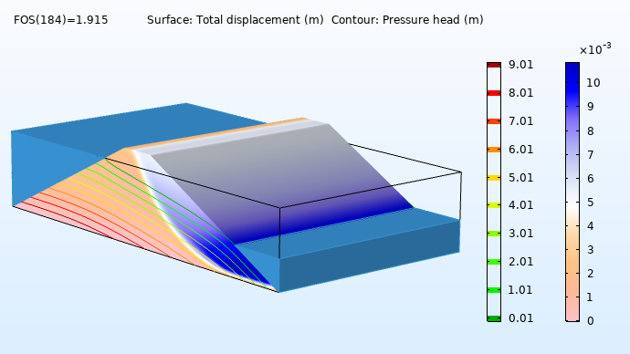
Total displacement just before slope collapse.
In general, slope stability can be used to evaluate the stability and safety of both manmade and naturally occurring dams and slopes. This type of analysis can be used to observe failure mechanisms due to loading conditions and call attention to other factors, such as vegetation and soil variability, which could affect naturally occurring slopes.
Next Steps
Try it yourself: Click the button below to access the tutorial model.
Further Reading
Check out these additional blog posts related to geomechanics:


Comments (0)