
Avoiding corrosion in a harsh ocean environment often requires the use of cathodic protection methods. These utilize different tools, such as sacrificial anodes or impressed currents, to help maritime-based industries stay afloat. One such system, impressed current cathodic protection (ICCP), mitigates corrosion by applying an external current to a ship hull. The efficiency of this method depends on factors such as the use of a coated propeller. Here, we use simulation to investigate how coating a propeller affects ICCP efficiency.
Nautical Corrosion
Sitting on the deck of a ship, you may be unaware of everything occurring underneath you. But if you were to dive beneath the waves, you might observe one of the biggest problems ships face: corrosion.
The corrosion you see on a ship’s hull occurs when there are areas with different potentials within an electrolyte — ocean water, in this case. Put simply, the ocean is an electrolyte that facilitates a flow of electrons from an anode with a higher electrolyte potential to a cathode with a lower electrolyte potential. This causes oxidation and corrosion in the anodic areas.
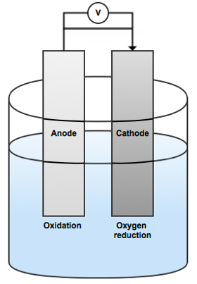
A simplified image showing an anode and cathode within an electrolyte solution.
Corrosion causes structures like ships and oil platforms to deteriorate and weaken. This may result in leakages and unsafe working conditions. Instead of trying to fix these issues after the fact, which can be costly, you can focus on avoiding corrosion before it happens with protection methods, such as ICCP.
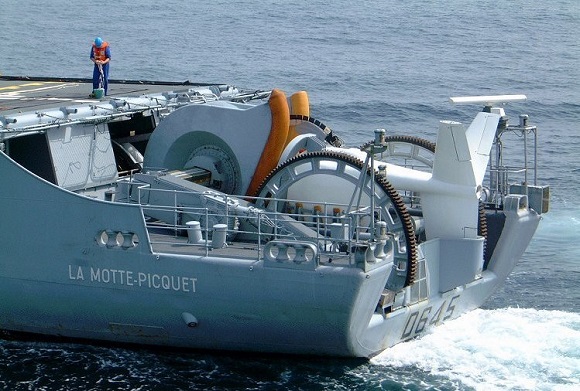
Ships like this one may utilize corrosion prevention systems to maintain structural integrity. (By Jean-Michel Roche. Licensed under Creative Commons Attribution-ShareAlike 3.0 Unported, via Wikimedia Commons.)
Mitigating Ship Hull Corrosion with ICCP
When using the ICCP method to protect the ship from corrosion, external currents are applied to convert high-potential anodic sites on a ship’s hull to low-potential cathodic sites. This ensures that the ship hull surface is protected from corrosion because the entire hull functions as a cathode.
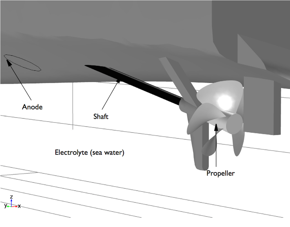
The geometry of a ship hull.
The amount of current needed for a functional ICCP system depends on a variety of factors such as salinity and the temperature of the water. However, the area of bare metal exposed to the sea water contributes the most to current demand. The propeller is often made up of exposed metal, but it could be coated. Whether or not the propeller is coated affects how much current is needed for the ICCP system to function.
Let’s turn to simulation to compare the efficiency of the ICCP system for a ship with a coated propeller versus a ship with an uncoated propeller.
Evaluating the Performance of a Coated Propeller with Simulation
To evaluate the use of a coated propeller in an ICCP system, we created a model inspired by a paper written by Huber and Wang.
Coated Propeller
In the coated propeller scenario, we test an applied current of 0.87 A. Here, the ship hull surface has a relatively uniform low electrolyte potential, while the anode surface has a higher electrolyte potential. This seems good so far, but let’s take a closer look at the less uniform area near the anode.
")
")
Left: The electrolyte potential for the tutorial model with a coated propeller. The anode is the red circle. Right: The local current density of the shaft for the coated propeller.
The shaft surface in our model shows a negative sign of local current density, which indicates an opposite current flow towards the shaft surface and not from it. This confirms that the shaft surface is undergoing a cathodic reaction.
With a cathodic reaction in the shaft surface, a higher electrolyte potential at the anode surface, and a consistently low electrolyte potential overall, the applied current density is enough for successful corrosion protection in the coated propeller scenario.
Uncoated Propeller
When simulating an uncoated propeller, we use an applied current of 3.1 A. Once again, the anode surface has a higher electrolyte potential than the rest of the hull surface. However, in this case, both the shaft and uncoated propeller surfaces have a lower electrolyte potential when compared to the rest of the ship hull surface.
")
")
Left: The electrolyte potential for the tutorial model with an uncoated propeller. The anode is the red circle. Right: The local current density of the shaft and uncoated propeller.
We can examine both the shaft and uncoated propeller surfaces and observe a negative sign of local current density. Due to this, we can assume that there is a cathodic reaction at both the shaft and uncoated propeller surfaces. Therefore, the current density is enough for corrosion protection in the uncoated propeller scenario as well.
While both coated and uncoated propeller scenarios were enough for corrosion protection, the coated propeller requires less current to prevent corrosion, making it the more efficient system. Additionally, the electrolyte potential is more uniform in the case of the coated propeller, as seen in the graph below.
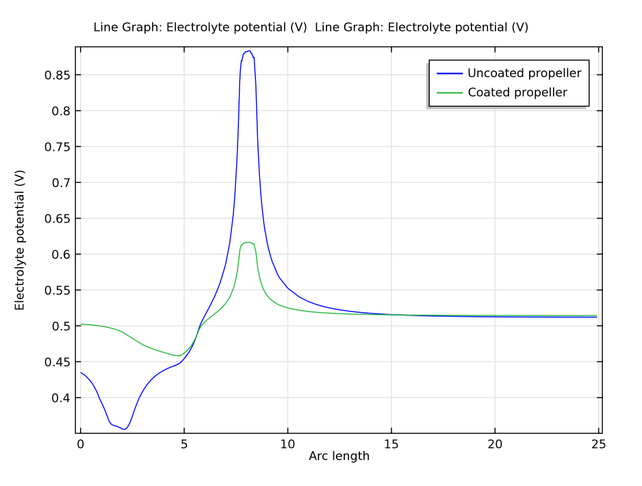
Plot comparing the electrolyte potentials for the coated and uncoated propeller models. The arc length represents the length of the ship’s hull.
Conclusion and Next Steps
Through our COMSOL Multiphysics simulations, we saw that the coated propeller hull surface is better protected than the uncoated propeller hull surface due to a consistently lower potential. It’s clear that the ICCP system functions better with a coated propeller.
Want to learn how to set up and run this model and analyze your own ICCP system? Download the tutorial from our Application Gallery. You can also easily modify this tutorial to simulate different types of cathodic protection systems, such as a system that uses sacrificial anodes without impressed currents.


Comments (1)
AMOL MALI
April 28, 2019HI ,
FRENDZ CAN WE DO TRIBOCORROSION ANALYSIS IN ANSYS