Perforations, in mufflers for example, enable partial sound transmission between chambers as well as in and out of pipes. When simulating perforates, it’s possible to draw and mesh each hole, but this increases the time it takes to solve the model. For a more efficient approach, we can apply a semitransparent boundary. Here, we’ll discuss several techniques for doing so as well as describe a method for computing the transfer impedance of the perforate.
Techniques for Representing the Perforate
Let’s say, for example, that you’re almost done drawing the geometry of a muffler model. It’s nothing too fancy, just a couple of cylinders representing the pipe and an extruded oval forming the main chamber. Then it strikes you: Some of the sections in the pipes and the baffles separating the chambers need to be perforated — and not just by placing a hole here or there. In this case, you could use the Array tool to draw an arbitrarily large collection of holes, but meshing and solving the resulting geometry would take too much time and memory.
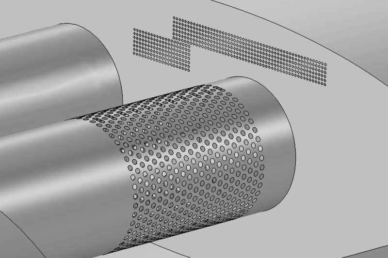
Detail of muffler geometry, including perforated sections consisting of a few thousand holes.
Fear not — there are better solutions. The simplest and most convenient approach is to draw the contours of the perforated regions and apply an Interior Perforated Plate condition. We then supply properties, such as the hole diameter and plate thickness, and get a partially transparent surface that represents the perforate.
In many cases, the accuracy of this method meets our simulation needs. However, the accuracy can be compromised if we push the limits of validity for the underlying engineering relation. For example, holes that are very small, lie too close to each other, or have a noncircular shape produce less reliable results.
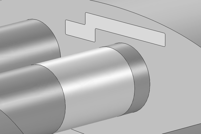
The same muffler geometry with the perforations now replaced by boundaries for applying a Perforated Plate or Interior Impedance condition.
A more general alternative to the Interior Perforated Plate condition is the Interior Impedance condition. This allows us to specify a complex-valued transfer impedance, which represents the ratio between the pressure drop across the perforate and the normal particle velocity through it. The Interior Perforated Plate condition is a special predefined version of the Interior Impedance condition. The value of the impedance can be based on imported measurement data or an analytical expression. If we lack trustworthy measurements of the transfer impedance or a good analytical expression, the impedance can be based on numerical results. This method, as described below, makes it simple to model the impedance numerically.
Computing the Perforate’s Transfer Impedance
The figure below shows the considered perforate in such a model, described in our Transfer Impedance of a Perforate tutorial. The principle behind this model is rather simple: We send a plane wave towards the hole and then calculate the transfer impedance from the resulting pressure difference across it and the average velocity through it.
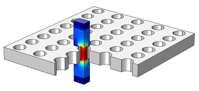
Representation of the perforate with the model domain colored according to the local acoustic velocity field.
The example model takes advantage of available symmetries, occupying only a quarter of the hole itself as well as half of the distance between holes. The holes in this case have a diameter of 1 mm, which is small enough that we must consider the thermoviscous boundary layers and losses. To account for these factors, we can use the Thermoviscous Acoustics interface.
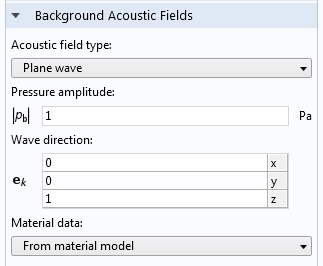
To send the plane wave, we utilize the Background Acoustic Fields node, a staple of the Pressure Acoustics interface that has recently been added to the Thermoviscous Acoustics interface. Its Plane wave option sends a pressure, velocity, and temperature distribution corresponding to a plane wave with viscous and thermal attenuation. We cap the model by adding perfectly matched layers above and below the model domain.
For even more on transfer impedances in perforated mufflers, we recommend the Thermoviscous Acoustic Impedance Lumping model. In addition to computing the transfer impedance of a perforate, this example demonstrates how to use the result in a model of an entire muffler, thereby summing up and driving home the message of this blog post.
See Additional Content Related to Acoustic Simulations
- Try out the highlighted tutorial: Transfer Impedance of a Perforate
- Read our Thermoviscous Acoustics blog series to learn more about the theory of thermoviscous acoustics and how to model it in COMSOL Multiphysics
- Check out all of the blog posts in our Acoustics category


Comments (2)
Ivar Kjelberg
October 3, 2016Hi and thanks for an interesting blog, now I remain “hungry” after this 😉
As I understand you, the perforated membrane is considered here as a “hard wall”, for the acoustics side, but what if the membrane is really thin and will also stretch and deform under the acoustic pressure, could you elaborate further on how we may make a periodic multiphysics model to take into account also this acousto-structure coupling, on a periodic sub-model, and then extrapolate to a general multiphysics model, solving for both acoustics and deformed structure ?
I have noticed its mostly rather easy to model a small sub-structure, but then I often have some doubts how to correctly implement it into a larger model, and how to verify this larger model.
Looking forward for the next Blog
Sincerely
Ivar
Linus Andersson
October 20, 2016 COMSOL EmployeeHi Ivar,
This is a very interesting question. For a bit of background, if you take the flexibility of regular, non-perforated muffler walls in account, the transmission loss tends to be similar to the rigid case over much of the frequency range. However, you do get pronounced spikes at the structural resonances. See for example https://www.comsol.com/model/absorptive-muffler-with-shells-14717.
I can’t say I know a whole lot about the topic, but I would imagine that you could expect similar behavior from making the perforated walls flex. To over- rather than underestimate the structural resonances, you could perhaps skip the perforation when running the model near the relevant frequencies. This turns the simulation into standard acoustic-shell interaction.
With a bit of work, I do think it should be possible to simultaneously include both the structural deformation of the perforate, and the sound transmission through its holes. I would suggest that you keep the unit cell model as it is, i.e. with a rigid wall. Then, in the model of the full muffler, you include a shell _and_ the transmission impedance from the unit cell. You would need to modify or override the automatic Acoustic-Structure Boundary condition to make this happen.