Exporting high-quality images from the COMSOL Multiphysics® software just takes a bit of know-how. Familiarizing yourself with the image export settings can help you produce images that are appropriate for your particular use, whether that is in a presentation, article, or paper — or on the web. Plus, once you get started, you may find a creative side you didn’t know was there.
Take your exported images to new heights.
Straight to the Point: Image Snapshot Settings
At any point in your modeling process, you have the ability to export an image snapshot of the Graphics window contents. In the Graphics toolbar, there is an Image Snapshot button with a camera icon. When clicked, a dialog box will appear with a host of settings for the image itself, as well as the layout. Depending on the settings you select, the settings you will want to use will vary. If you’re just interested in exporting a high-resolution model results image without any text, the settings shown below will suffice.
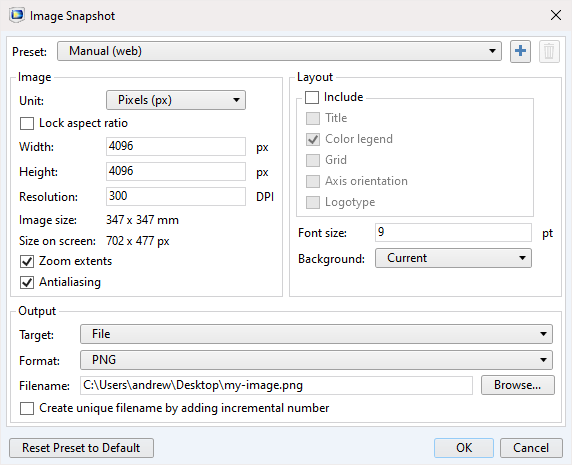
Image Snapshot dialog box showing the export settings.
Image Export Settings and Recommendations
Before getting into what settings to use for different purposes, let’s go over the settings themselves.
| Setting | Description |
|---|---|
| Preset | Exports the image at the current size, or with predefined settings for web, print, or saved presets |
| Unit | Select the measurement for the image size (mm, in, px) |
| Resolution | Enter the DPI (dots per inch) |
| Zoom extents | Exported image will show the full geometry, irrespective of the current Graphics window view |
| Antialiasing | Minimizes the jagged edges and other distortions |
| Layout/Include check boxes | Adds the selected options to the image |
| Target | Export to a file, copy to the clipboard, or export directly to PowerPoint |
| Format | Export as a BMP, EPS, JPEG, PNG, TIFF, GIF, or glTF™ |
The Width, Height, Font size, and Background settings are self-explanatory.
For the Unit, we recommend using Manual (web) for the size and Pixels (px), unless you are printing the image for a poster or other hard copy resource. The number of pixels is the limiting factor, a maximum of 4096 for both height and width.
The Resolution setting affects multiple aspects of the exported image, including the edges of the model geometry, the title, legend, and grid. The higher the DPI, or PPI (pixels per inch) for web, the thicker the lines, text, and legend will be. When exporting images for print, a resolution of 300 DPI is standard, and you can enter a width/height of up to 346.8 mm or 13.65 inches (before exceeding the maximum of 4096 pixels). A general best practice for exporting images for web is to use the preset, Manual (web), and to increase the resolution at the same ratio as the width of the image.
For the export format, note that EPS applies only to 1D plots, glTF™ applies only to 3D images, and the GIF format here is a single image as opposed to an animation.
Exporting Images for Conveying Information
When it comes to the finer details of exporting images, there is a key decision to make. Are you exporting the image for aesthetics or clarity? That is, do you simply want your image to look good, or do you want the image to convey valuable information?
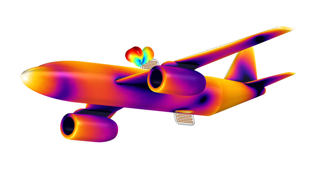
As previously mentioned, if you are exporting an image for aesthetics (without any text), the best settings are a height and width of 4096 x 4096 and 300 DPI, with the antialiasing check box selected. Whether you want to zoom extents, focus on a specific part of the geometry, or use a transparent background depends on your preferences. Of course, you may want to adjust the aspect ratio (width and height) depending on the model geometry shape, such that the image fills the container.
We often include text in our images to convey information about the plot. Text will appear when adding a title or color legend (3D, 2D) or information legend (1D), as well as when employing the Annotation feature. There are two settings that will affect the size of the text: Font size and Resolution. As an example, the image below has a width of 690 pixels, which matches the width of the blog’s frame (the blog you’re reading right now), so the image is not resized, and the 96 DPI and 9 font size match that of COMSOL Multiphysics, ensuring clear text.
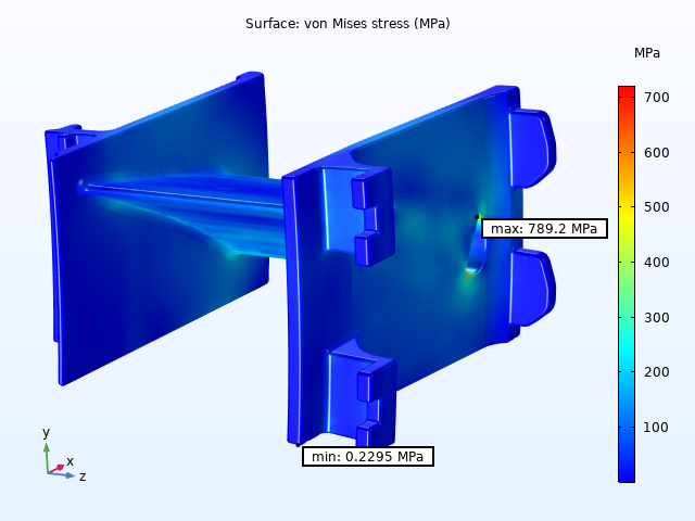
The turbine stator model image exported at 640 x 360 pixels with 96 DPI and a font size of 9, shows the von Mises stress on the surface of the model, as well as the maximum and minimum stress values.
As images get larger, so must the values for the resolution and font. Slide decks, webpages, and Microsoft® Word documents, for example, require images with higher resolutions. The image below has settings meant for someone to see in a full screen. While it doesn’t look as nice in this blog post, it looks much better if you click to enlarge.

The solar panel model image exported at 1920 x 1200 pixels with 150 DPI and a font size of 12, showing the velocity streamlines of the flow and displacement of the panels.
Closing Thoughts on Model Images in COMSOL Multiphysics®
Understanding how the image export settings function is crucial to producing high-quality images. With a little bit of practice and tinkering, exporting images can be a breeze. If you have further questions about exporting images for various uses, feel free to comment below!
gITF is a trademark of The Khronos Group Inc.
Microsoft is either a registered trademark or trademark of Microsoft Corporation in the United States and/or other countries.


Comments (3)
Nicolas Luchier
October 12, 2020Hi,
Thanks you for the post. I’d have a question:
I’d need to produce 2D images of the same results for different parameters values, one parameter by COMSOL file. I would like to have a uniform set of images with the very same zoom and the very same x and y range. For now, I proceed through trials and errors. Is there a mean to set a zoom value and space range?
Thanks,
Nicolas Luchier
Andrew Griesmer
October 12, 2020 COMSOL EmployeeHello Nicolas, you are able to access and edit the appropriate settings in the View node (either under the Definitions or Results node). Select the Axis node under the View node to see the x and y range.
Mitchell Glodowski
November 5, 2020Awesome Post!
I am wondering how to remove outer domain boundary lines while being able to slice data which uses those domain boundaries.
Thanks,
Mitchell