
Radioactive materials have a long half-life, so they must be stored safely — usually in steel drums. These drums are then stored in confinement systems, which are designed with safety in mind (so that they can resist, for instance, a fire event exceeding two hours). Sogin, the state-owned company responsible for the Italian nuclear sites decommissioning and radioactive waste management, evaluated the fire resistance of a confinement system overpack using the COMSOL Multiphysics® software.
Managing Nuclear Waste
The confinement system overpack, specific for containing radioactive waste, has an overall thickness that allows for an increased resistance up to 120 minutes in the hypothesis of a possible fire. In particular, Sogin engineers analyzed their design using the COMSOL® software and also validated and certified the results with experiments.
Typically, radioactive waste is a byproduct of the energy produced by fission in a nuclear reactor. During the fission process, different types of energy are released and converted into thermal energy. To deal with this energy, engineers must account for the complex and coupled phenomena in a nuclear reactor, including phase change as well as multiphase and turbulent flow. But managing radioactivity doesn’t stop there: When the nuclear cycle is through, engineers must also consider what to do with the spent fuel and the potential problems associated with storing such a volatile material. While radioactivity does decay over time, this process can take hundreds of years, and the waste needs to be isolated until it no longer poses a threat to the surrounding environment.
To prevent potential problems, governments regulate the storage and disposal of nuclear waste. Radioactive waste is categorized by the radioactive isotope type and its lifespan, and these factors determine how the waste is disposed of, including:
- How long it’s stored before disposal
- How deeply it’s buried underground
- Where it’s buried
- Whether transmutation is necessary
Depending on the category, regulations cover different types of transport and storage, and tests are performed that subject the container to different types of stress.
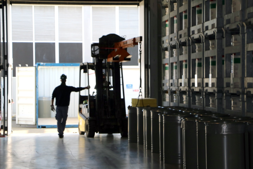
A Sogin temporary storage container for radioactive waste. Image courtesy Sogin.
To adhere to regulations, engineers can design optimized confinement systems for the waste, which is usually stored in containers like drums. These systems are designed to prevent the release of nuclear activity into the environment.
A group of engineers from Sogin in Italy decided to test the design of a confinement system against regulations for a fire event. According to the U.S. Department of Energy (DOE) standard addressing fire protection and the results of nuclear risk analysis, a structure must be able to withstand fire exposure for a minimum of two hours. To ensure that they met this goal, the engineers used numerical analysis to evaluate the fire resistance of an overpack in a confinement system for different cases. They then verified the simulations and certified the overpack with their own experiments.
Analyzing a Fire-Resistant Overpack Design
Sogin, a state-owned Italian company, needed to store radioactive waste in one of its temporary storage facilities until the waste could be definitively stored in a national repository. Because the building already existed, the storage space available was limited, presenting strict geometrical restraints. “Existing buildings,” the Sogin team said, “need to be adequate to install the new systems and sometimes to improve structural resistance to new standard code requirements.” There was another challenge: Sogin had to make sure that the containment system around the drum could not only withstand a fire but protect the waste from the flames for at least two hours.
Before storage, the dismantling products can be physically or chemically decontaminated in order to optimize the repository usage. For their experiments, the Italian engineers chose to use polymeric-fiber-reinforced concrete (PFRC) for the overpacks, which could improve the packs’ structural integrity (reducing spalling phenomena) and limit the temperature rise inside the drums. As shown below, a typical confinement system is dome-shaped; consists of an outer shell, an insulating ceramic, a blanket, and an overpack; and goes around a drum containing nuclear waste.
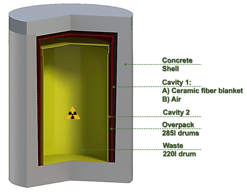
Schematic of a confinement system. Image courtesy Sogin.
To start, the engineers investigated two different thermal cases, concentrating on the inner gap (Cavity 1) between the concrete overpack and the drum:
- Case A — Drum is filled with a ceramic fiber blanket (thickness of 25 mm)
- Case B — Drum is filled with air (cavity 1 thickness from 25 mm to 40 mm)
Setting Up the Numerical Analysis
Sogin engineers set up the material properties, which are temperature dependent, according to the European standards for moist concrete, carbon steel, and stainless steel. As for the properties of the ceramic fiber blanket, they used supplier data. A standard curve based on the regulation ISO 11363-1:2018 was used to describe the two-hour fire event. To account for water evaporation as well as the presence of polymeric fibers, the team defined a specific heat capacity of concrete function of temperature.
For both cases, they applied boundary conditions that included an initial temperature set to 290 K and pressure constraints for the air cavities, with the concrete shell resting on a concrete slab. Two different meshes were used for Case A and Case B. In both models, the fluid flow was computed with the low Reynolds number k-ε closure model. (For more information on the equations, material properties, boundary conditions, and mesh used in these models, read Sogin’s paper.
Sogin then performed a numerical analysis on an axisymmetric model using the Heat Transfer Module and Structural Mechanics Module, add-on products to the COMSOL Multiphysics® software. This analysis was carried out in two steps:
- The Heat Transfer Module was used to perform a heat transfer transient study, with a single-phase compressible flow governed by the Navier-Stokes equations
- The Structural Mechanics Module was used to perform a stationary structural mechanics study to examine the thermal stresses caused by the temperature field obtained in the previous study
Setting Up the Experimental Test
The team at Sogin decided to run their own experiments partly because the overpacks that were commercially available had different sizes and characteristics than what was needed to meet standards. They decided to use this opportunity to improve the performance of overpacks using fiber-reinforced concrete. The experiment enabled them to evaluate the model response while meeting the standard requirements necessary to certify the product.
Using a certified laboratory, the project team prepared to test two prototypes, one for Case A and one for Case B. The experimental oven, measuring 4000 mm by 3000 mm, had a fire curve comparable to the standard, and the oven was equipped with four burners and thermocouples. The team also added four thermocouples on each prototype, positioning them to measure the temperature on each surface of interest. The internal pressure of the oven was also monitored closely.
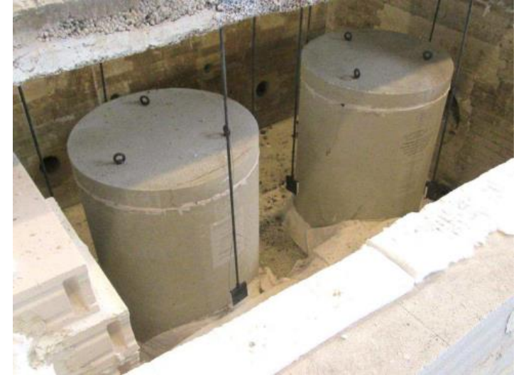
The experimental setup of the concrete shells. Image courtesy Sogin.
Before running the test, they conducted a final, visual inspection of the concrete shells for each prototype, confirming their structural integrity.
Comparing the Simulation and Experimental Results
First, Sogin engineers evaluated the results of the heat transfer study. They looked at the simulation results and the experimental data for Cases A and B, evaluating the inner surface temperature as well as comparing the temperature profile on a cut line with the average temperature measured on the thermocouples at 120 min. They found that the difference between the numerical and experimental results was minimal — less than 10% for both cases, thus verifying the accuracy of the numerical analysis.


Case A (top) and Case B (bottom) comparisons. The left images show the average temperature of the inner surface of a concrete shell, comparing the numerical analyses (lines) and experimental data (dots). On the right, there’s the temperature profile for a cut line at z = 850 mm (light blue lines) and the thermocouples (blue dots). Images courtesy Sogin.
They then examined the results of the structural mechanics study. First, the engineers examined the fluid velocity field. The velocity magnitude of the streamlines, shown below, is highest in Cavity 1, with a maximum calculated velocity (shown in red) of 0.45 m/s. While this result is from Case B, the team found that both cases satisfy regulation requirements.
Animation of the fluid velocity field for Case B courtesy Sogin.
Next, the team evaluated the thermal stresses and displacement field at 120 min for both cases and compared the numerical analyses with the prototypes. When examining the thermal stress results for Case B (below on the left), it’s clear that the tensile stresses are distributed more evenly on the inner surface walls of the confinement system and are concentrated at the bottom of the system. (The team designed steel reinforcement bars to account for the thermal stress distribution and steel temperature.) As for the displacement field for Case B (below on the right), the results show that the bottom of the concrete shell works at the lowest temperature and represents a constraint for the deformation of the walls, confirming that the bottom of the shell is not too affected by increasing temperatures.


Von Mises stresses (left) and displacement field (right) for Case B. Images courtesy Sogin.
Overall, the Sogin engineers found that the numerical analyses compared favorably with their experiments, demonstrating that simulation can provide accurate results. The slight differences are easily explained. For instance, the team used thermal property values for standard concrete instead of PFRC; might not have had the exact positioning of the burners and thermocouples in the simulation; and did not entirely account for water evaporation and moisture diffusion. To correct these differences, future investigations may include modeling the moisture transport in porous media and fluids — enabling the engineers to optimize the design of a fire-resistant overpack to keep nuclear waste contained.
Next Steps
Get more details on Sogin’s research by clicking the button below:
Learn more about nuclear fuel on the COMSOL Blog:


Comments (0)