Simulating MEMS Accelerometers and Gyroscopes Used in Inertial Measurement Units

These days, most people don’t begin a journey without a navigation device connected to the Global Positioning System (GPS). But GPS signals can be interrupted when a vehicle goes underground or among tall buildings. That’s why many vehicles, mobile phones, and other devices carry inertial measurement units, or IMUs. An IMU uses incredibly small and precise gyroscopes and accelerometers to determine motion in relation to x-, y-, and z– orthogonal axes of the earth. The components of an IMU, including MEMS gyroscopes and accelerometers, can be modeled using the COMSOL Multiphysics® software.
“You Are Here” Meets “This End Up”
Picture a deep black sky, its darkness relieved by thousands of white dots, arranged in a shape that reveals itself as the Milky Way. And above our galaxy, an arrow points at one of the little dots, with text that unhelpfully reads, “YOU ARE HERE”.

An example of a navigational instrument with an unhelpful frame of reference.
This old visual joke, which may have appeared on as many nerdy T-shirts and professors’ doors as there are stars in the sky, does hint at some truths about the relativistic nature of navigation (and life!) Perhaps its primary lesson is that an object’s location can only be usefully described in relation to the space that surrounds it. In navigation, that space is the frame of reference.
When we plot our course on a road map, we’re navigating within a two-dimensional frame of reference. A map alone can’t tell us if we’re moving up or down a hill, or if our vehicle is at risk of rollover. An IMU-equipped navigation system can compute a vehicle’s trajectory in three-dimensional space by measuring both linear and angular acceleration. With three accelerometers each oriented along the x-, y-, or z-axis, we can track linear motion in 3D space. Likewise, with three gyroscopes each oriented along the x-, y-, or z-axis, we can measure rotation in 3D space. (Ref. 1)
Rocks in Your Head? They’re Part of Your Accelerometers
If you do something foolish, you might be asked, “Do you have rocks in your head?” If that happens, you can truthfully reply that yes, we all do, and even fools should know that they’re very important! Every vertebrate’s body contains microscopic otoliths made mostly from calcium carbonate — the main ingredient in limestone. (Otolith is Greek for “ear stone”.) These rocks in our heads are integral parts of our bodies’ natural accelerometers. (Ref. 2)
An accelerometer consists of a proof mass, suspended on a flexible structure that’s attached to a housing. When the housing experiences acceleration, so will the proof mass, causing measurable strain on the suspension. For the accelerometers inside our ears, the proof mass is a bundle of otoliths. This bundle is attached to a membrane that is suspended from microscopic hairs and attached nerves, which will pick up on electrical changes when the mass shifts. This organic accelerometer is attached to our inner ear structure, which serves as the frame of reference.
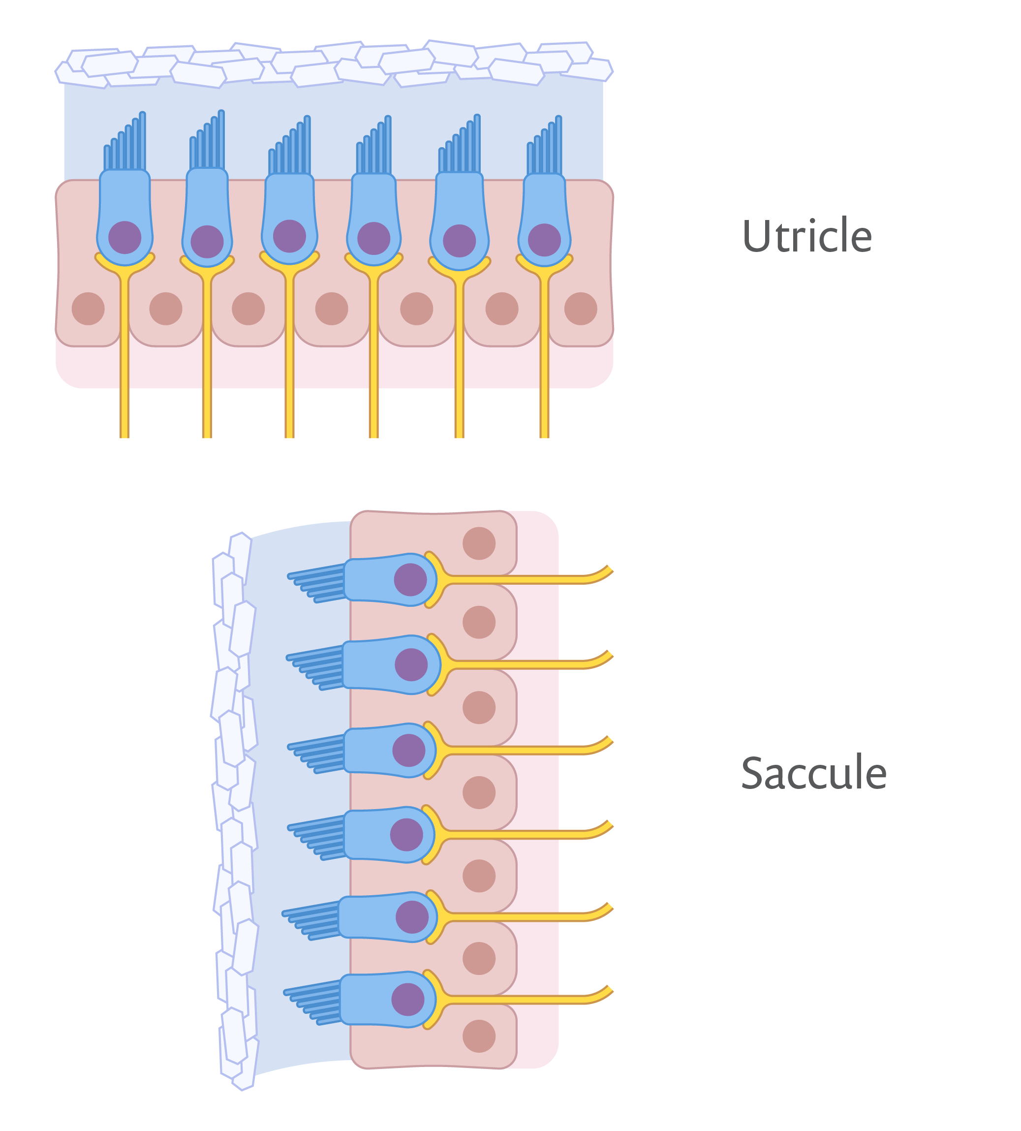
The human body contains a horizontally positioned utricle and a vertical saccule in each ear. Each of these microscopic structures contains a suspended proof mass, which stimulates attached nerves in response to acceleration. (Ref. 3)
When our bodies move abruptly, the proof mass’ displacement alerts our nerves to the potential for falling. Our nerves can thereby detect motion in our bodies even when other sensory organs, like our eyes or ears, lose track of their reference frames. The surface micromachined accelerometer serves a similar function for devices and vehicles.
“Building Blocks” for Modeling a MEMS Accelerometer
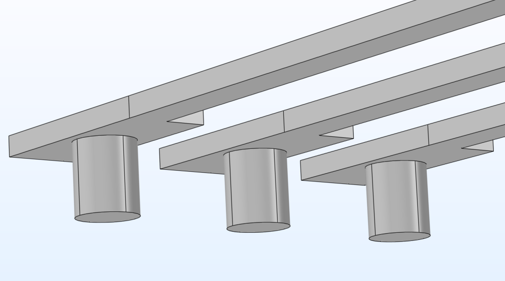
The tutorial model presented here shows how to model a surface micromachined accelerometer using the Electromechanics multiphysics interface of the MEMS Module. The model consists of three subassemblies: the proof mass, the anchored springs that support the proof mass, and the electrode array. Browse the slideshow to see all three subassemblies as well as the full model.
 Building block for the proof mass with attached electrodes.
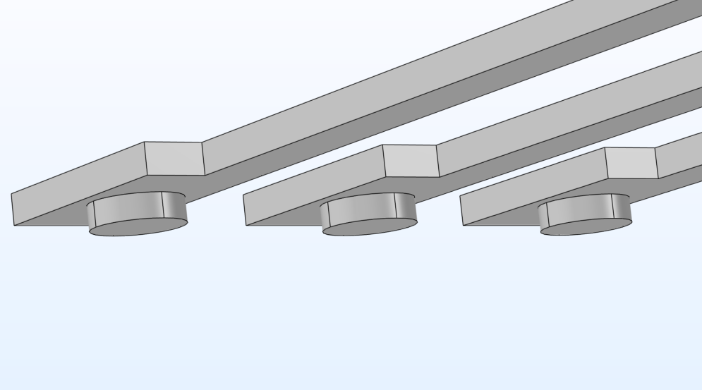
 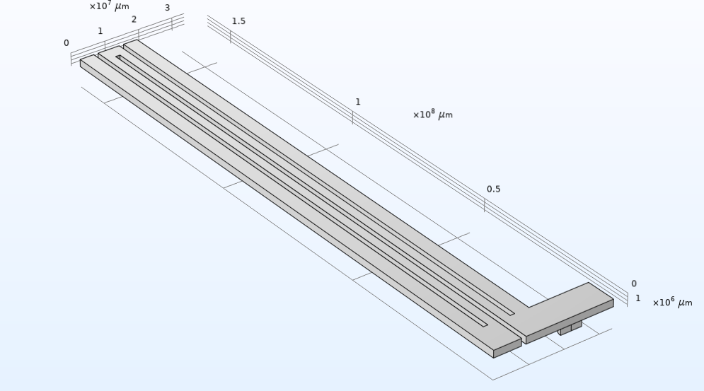 Building block for the anchored spring.
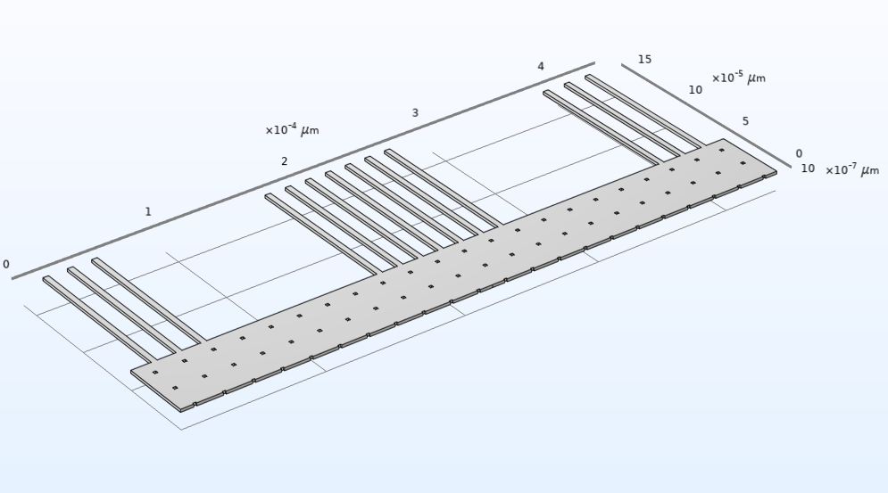
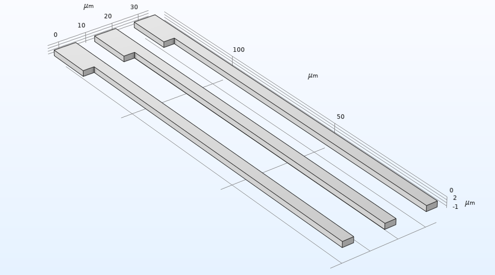 Building block for the fixed electrode array.
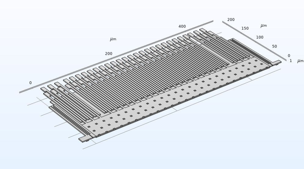 The entire geometry of the surface micromachined accelerometer model.


When the device experiences acceleration, the proof mass will be displaced, thereby changing the capacitance between the fixed and moving electrodes. This change in capacitance is proportional to acceleration.
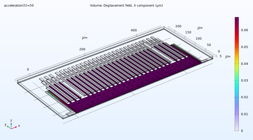
Displacement under applied acceleration of 50 g. In this scenario, the proof mass moves by about 0.07 micrometer.
When defining the model, you can specify dimensions, orientation, and other attributes for the three core modules of proof mass, springs, and electrodes. You can test different design options by adjusting the values of the key attributes for these modular building blocks, also called subsequences. This modularity supports simulated prototyping and testing of the accelerometer’s components and their configuration.
At left, a modular “building block” electrode array for the accelerometer model. The redesigned array at right was made from the same modular subsequence by adjusting key attributes.
The Ups and Downs of Tuning Fork Gyroscopes
Just as nature has equipped some animals with accelerometers, others carry their own gyroscopes! Houseflies, mosquitos, and some other flying insects have two appendages called halteres, which you can see behind the wings of this crane fly:
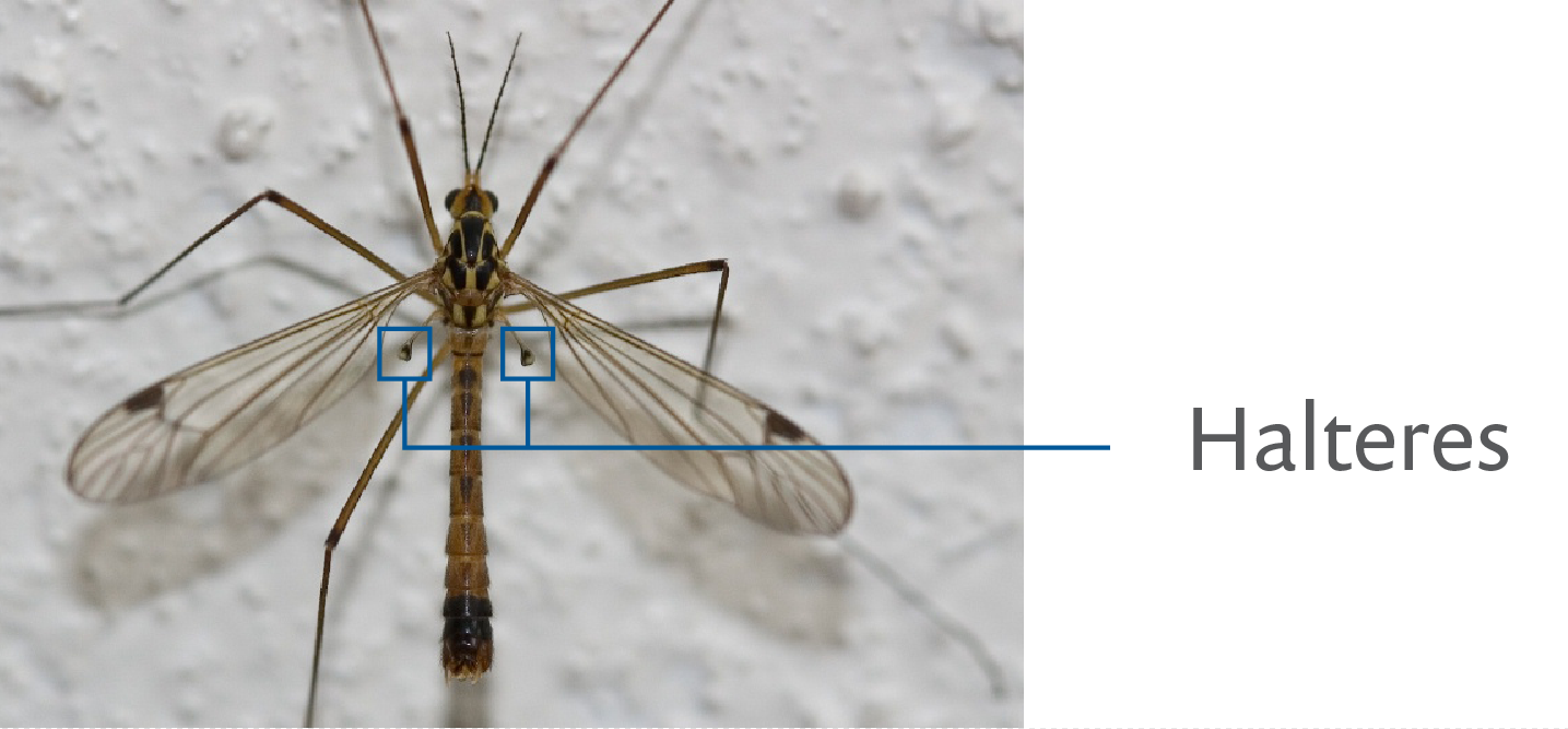
A top view of a crane fly, showing the location of its halteres. Original image by Andre Vrijens, licensed under CC BY 3.0 via Wikimedia Commons.
An insect’s halteres flap rapidly in time with its wings. In level flight, this motion will trace an up and down path. But when the bug tilts its body, the halteres’ path will shift due to the Coriolis effect. This will cause the halteres to move right and left as well as up and down. The insect perceives the halteres’ shifting movements via the pressure they place on attached hairs. This information enables it to control its orientation relative to its flight path.
A piezoelectric rate gyroscope works according to similar principles. Let’s explore a model to learn how.
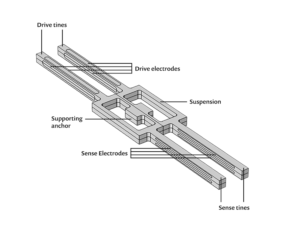
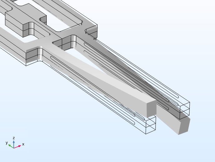
A schematic of the modeled tuning fork gyroscope, showing the plane of symmetry through the center of the device and the key components.
The rectangular shape at the center of the gyroscope is its suspension. This element’s supporting anchor is rigidly attached to the device in which the gyroscope is installed. The two pairs of protruding elements are the drive tines and sense tines. Electrodes on both sets of tines enable them to provide useful data about the orientation of the device.
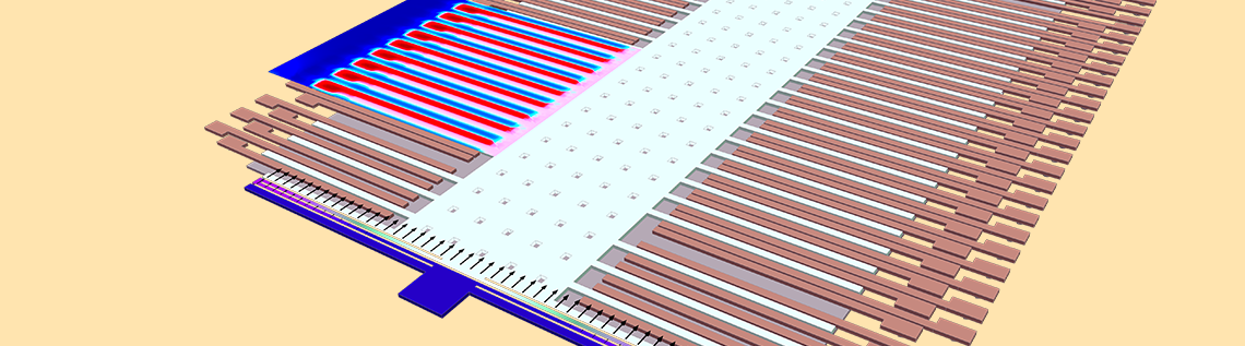
To explain how this works, let’s consider how the tines behave when the device is either stationary or in uniform motion (motion without linear or rotational acceleration) with respect to its frame of reference. We will then look at how the tines’ behavior changes when the device is in rotation. An electric signal applied to the drive tines causes the sense tines to vibrate at their resonant frequency in the xy plane. When the device is rotating about the y-axis, Coriolis force will result in out-of-plane vibration, as shown below.
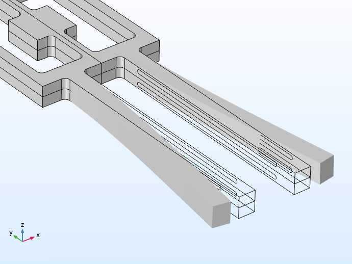
At left, applying current when the device is in uniform motion causes the tines to vibrate along the xy plane. At right, device rotation about the y-axis causes out-of-plane vibrations along the z-axis.
Note that the drive tines and sense tines have different resonant frequencies. When the gyroscope is in operation, electrodes in the drive tines stimulate them to vibrate at their resonant frequency via the reverse piezoelectric effect. When the entire device rotates about the y-axis, the resulting Coriolis force will excite the sense tines to vibrate out of plane, and this movement will generate current in the sense tines’ electrodes via the direct piezoelectric effect.


The image on the left shows two plots of the device in uniform motion, without acceleration or rotation. Note that the tines are vibrating in the xy plane. On the right, the device is rotating about the y-axis, which causes the tines to vibrate out of the xy plane. In both images, the plot on the left shows color variations to indicate magnitude of displacement, whereas the right shows actual displacement of the tines in space.
An animation of the tines’ behavior when the device rotates about the y-axis, causing out-of-plane vibration. On the left, color variation indicates magnitude of displacement, while the image at right shows movement in space.
You Are Here, at the End (and a Beginning…)
Thanks for navigating your way to the end of this post! Your journey through the modeling of MEMS accelerometers and gyroscopes can continue via the links below:
- Speed over to the accelerometer model: Surface Micromachined Accelerometer
- Take the gyroscope model for a spin: Piezoelectric Rate Gyroscope
More on Modeling Piezoelectric Devices
- Modeling Piezoelectricity: Which Module to Use?
- How to Model Piezoelectric Devices as Both Transmitters and Receivers
- Simulating a MEMS-Based Pressure Sensor Inspired by a Cave Fish
References
- B. Schweber, “The Autonomous Car: A Diverse Array of Sensors Drives Navigation, Driving, and Performance”, https://www.mouser.com/applications/autonomous-car-sensors-drive-performance/
- D. Purves, G.J. Augustine, D. Fitzpatrick, et al., editors, “The Otolith Organs: The Utricle and Sacculus”, Neuroscience. 2nd edition. Sunderland (MA), Sinauer Associates, 2001; https://www.ncbi.nlm.nih.gov/books/NBK10792/
- T. C. Hain, “Otoliths”, Mar. 2021; https://dizziness-and-balance.com/disorders/bppv/otoliths.html


Comments (0)