The flow of fluid through a porous medium is usually described by Darcy’s Law. However, what if you wanted to look at a combination of fluid flow, heat transfer, and mass transport in a porous medium? Instead of using Darcy’s Law, which calculates an average linear velocity for fluid flow in porous media, the Navier-Stokes equations would be necessary in order to obtain accurate results. In addition, heat convection and conduction, as well as mass transport would need to be taken into account. Researchers from the Georg-August University in Göttingen set out to create just such a simulation to analyze this complex multiphysics system, and to answer this question: Can mass transport in porous media be predicted when the only information available about a system is heat transfer, and vice versa?

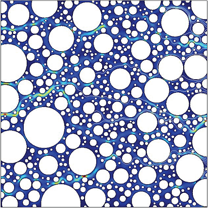
Figure 1. Typical example of simulated fluid flow through porous media;
colors represent velocity magnitude (red=high, blue=low) calculated using the
Navier-Stokes equations. A pressure drop has been applied from the right to
left sides of the flow field. Image provided by: E. Holzbecher, S. Oehlmann,
Georg-August University Göttingen.
Mass Transport, Heat Transfer, and Fluid Flow in Porous Media
When studying transport in porous media, heat and mass transfer are often compared in order to understand their behavior in both natural and artificial porous systems. Analyzing heat transfer, mass transport, and fluid flow in a porous medium has many applications, ranging from the studies of geothermal reservoirs and biological tissues, to petroleum engineering and bio-remediation. Researchers from the Georg-August University in Göttingen created a simulation to study heat transfer to mass transport in porous media, and to provide a clearer picture of their relationship that could be used in many of these application areas. They proposed that if a measurable relationship existed, it would enable the use of tracers to predict heat flow in a porous medium. Conversely, it could allow heat transfer to be used as an indicator of the flow of contaminants, nutrients, and other substances through the porous medium. To determine if this relationship existed, they created a simulation detailing these interactions, and their results suggest a uniform behavior for heat transfer and mass transport in porous media at different scales.
Simulating Heat and Mass Transport in Porous Media
When setting up their simulation in COMSOL Multiphysics, Georg-August University researchers chose a geometry with varying lengths (L) between 1 mm and 100 mm, and a porosity in the mm to dm scale, leaving corresponding pore spaces in the range of μm. Additionally, the researchers noted that in porous media at the micro-scale, heat transfer and mass transport differ in two major respects. First, heat transfer takes place in both the fluid and solid phases, while mass transport is only possible in the pore space. Second, the parameters for heat and mass diffusion differ by a factor of 103, and therefore the Lewis number is given as the thermal diffusivity/molecular diffusivity. Both of these factors were taken into account in the model. The porous medium was constructed in 2D and a random number generator was used to determine pore positions and size; the geometry was randomly filled with non-intersecting spheres until a specific porosity was reached. The simulation was run for two different lengths, L=0.001 m and L=0.01 m.
Before analyzing the heat and mass transfer in the porous media, a fluid flow analysis in the pore space was computed, which showed the preferential flow paths of the fluid flow in the porous medium. A typical output for this study is shown in Figure 1, above.
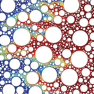
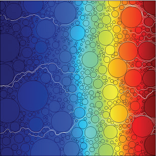
Next, the researchers ran the mass transport simulation. Figures 2 and 3 show the results for two different geometries; snapshots were taken when the mass was mostly concentrated near the center of the geometry.

|

|
| Figure 2. Concentration distribution for mass transport at length L=0.001 m; snapshot at t=800 s. Image provided by: E. Holzbecher, S. Oehlmann, Georg-August University Göttingen. | Figure 3. Concentration distribution for mass transport at length L=0.1 m; snapshot at t=230 s. Image provided by: E. Holzbecher, S. Oehlmann, Georg-August University Göttingen. |
As the simulations show, there is a significant difference in mass transport for the two differently-sized geometries. In the smaller geometry, shown in Figure 2, the mass transport is largely homogeneous, with no clear preferential flow paths. However, in the larger geometry (Figure 3), there are preferential flow paths where mass is concentrated. Therefore, advection dominates the mass transport in the larger geometries. The researchers propose that this phenomenon is due to the fact that the average pore-space length has increased in the larger geometry. This also explains why the travel time for the larger system is shorter (t=230) compared to the smaller system (t=800 s).
The researchers next looked at the temperature diffusion in the two systems. The results are shown in the figures below:

|

|
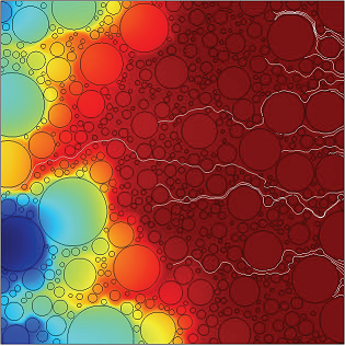
| Figure 4. Temperature distribution for heat transfer at length L=0.001 m; snapshot at t=1 s. Image provided by: E. Holzbecher, S. Oehlmann, Georg-August University Göttingen. | Figure 5. Concentration distribution for heat transfer at length L=0.1 m; snapshot at t=500 s. Image provided by: E. Holzbecher, S. Oehlmann, Georg-August University Göttingen. |
In Figure 4, we can see a thermal front that moves with a velocity independent from the distribution of the pores. In this system, the travel time for the front is significantly smaller than the travel time for mass transport in the corresponding system. The researchers found that the ratio between travel times is almost three orders of magnitude shorter, which corresponds to the ratio of diffusivities as measured by the Lewis number.
In the larger system (Figure 5), heat transfer is dominated by convection, just as mass transport in the larger system (Figure 3) was dominated by advection. Figure 5 shows that heat transfer follows the preferential flow paths that influence the mass transport. In this system, the travel time corresponds with the length L of the system, and travel time is longer than in the smaller geometry.
From these findings, the researchers concluded that for a length scale lower than 1 mm, when the system is dominated by diffusion, mass transport is much slower than heat transport. On a larger scale however, heat transfer is slower compared to mass transfer.
Further Reading
- Download the full paper: “Comparison of Heat and Mass Transport at the Micro-Scale“
- Check out more papers from the COMSOL Conference 2012 User Presentations webpage


Comments (0)