While measuring the S-parameters of a circuit using a network analyzer in a laboratory, calibration is performed to extract the pure characteristics of the circuit without measurement equipment and cables. However, the calibration considers the cable end to end with connectors mounted on the circuit, while the simulation model excludes the connectors to keep the computations simple and fast. Say we want to study the response of the circuit only, like the simulation model setup, without the connectors. But how?
The Closer to Reality, the More Reliable the Numerical Analysis
In order to accurately describe the lab measurements mentioned in the example above, the simulation model needs to include connectors. It would be cumbersome to build that type of geometry every time you want to model a multiport device. Instead, a predefined geometry popularly used among device designers and test engineers would easily overcome this barrier.
The RF Module, an add-on to the COMSOL Multiphysics® software, includes specialized features for high-frequency electromagnetics simulation, including a Part Library consisting of a number of standard parts and geometries. Each part has controllable parameters so you can change geometric configurations and predefined selections, which can be utilized to update physics settings, material properties, solver settings, and postprocessing operations.
Some of the geometries frequently used in RF modeling include:
- Various types of connectors
- Surface mount devices
- Waveguides
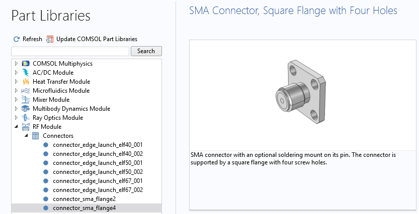
The Part Library window when adding a part to a geometry.
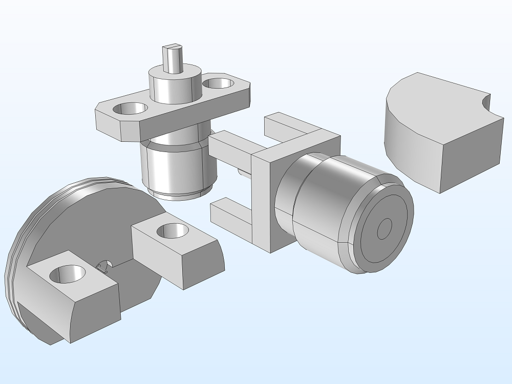
View of parts after they are added to the Geometry node: An edge launch connector, a two-hole flange SMA connector, a PCB mount SMA connector, and a 90-degree bent WR28 rectangular waveguide.
These parts are partially parameterized complex shapes that are useful for circuit and antenna simulations. Predefined selections — a group of boundaries — in each part help to set up the physics, especially for conductive or lossy metallic boundaries. The benefit of using these parts is that you don’t have to create the geometry from scratch, which saves you a substantial amount of time.
Let’s go over two examples…
Bridging a Test Device to Measurement Equipment Using an SMA Connector
SMA connectors work very well as a transition between coaxial cables and printed circuit boards (PCBs). They are popularly used in a laboratory when measuring RF signals in microwave applications.
Three types of SMA connectors are available in the RF Part Library. The parameterized portions in each part let you make any edits to its shape and size so that they meet design specifications.
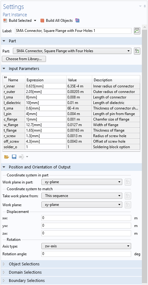
Settings window of a four-hole flange SMA connector after it is imported from the Part Library. It is possible to make different shapes from the geometry simply by changing the parameters.
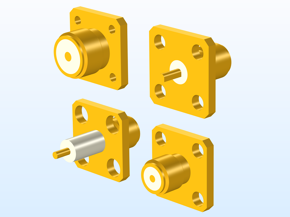
Variety of four-hole SMA connectors with different input parameters.
The initial position and orientation of the part geometry are not ready to be used for an arbitrary design of a device. Instead, these parameters can be easily adjusted in the part’s Settings window and quickly deployed on the device.
Several Application Library examples use SMA connectors from the RF Module Part Library, providing more convenience while setting up a model for simulation. (The Application Gallery links to these examples are listed at the end of this post.)


Left: Two-hole flange SMA connectors on a branch-line coupler. Right: Four-hole flange SMA connectors on a Wilkinson power divider.
Suppressing Undesirable Loss in a Millimeter-Wave Device with an Edge Launch Connector
Conventional SMA connectors suffer from radiation, insertion loss, and impedance mismatching problems when the operating frequency is close to the millimeter-wave range. It is possible to overcome these deficiencies by using solderless, push-on-type connectors.
The special design mechanism of an edge launch connector makes its deployment well suited for millimeter-wave applications such as 5G and satellite communication (SatCom).
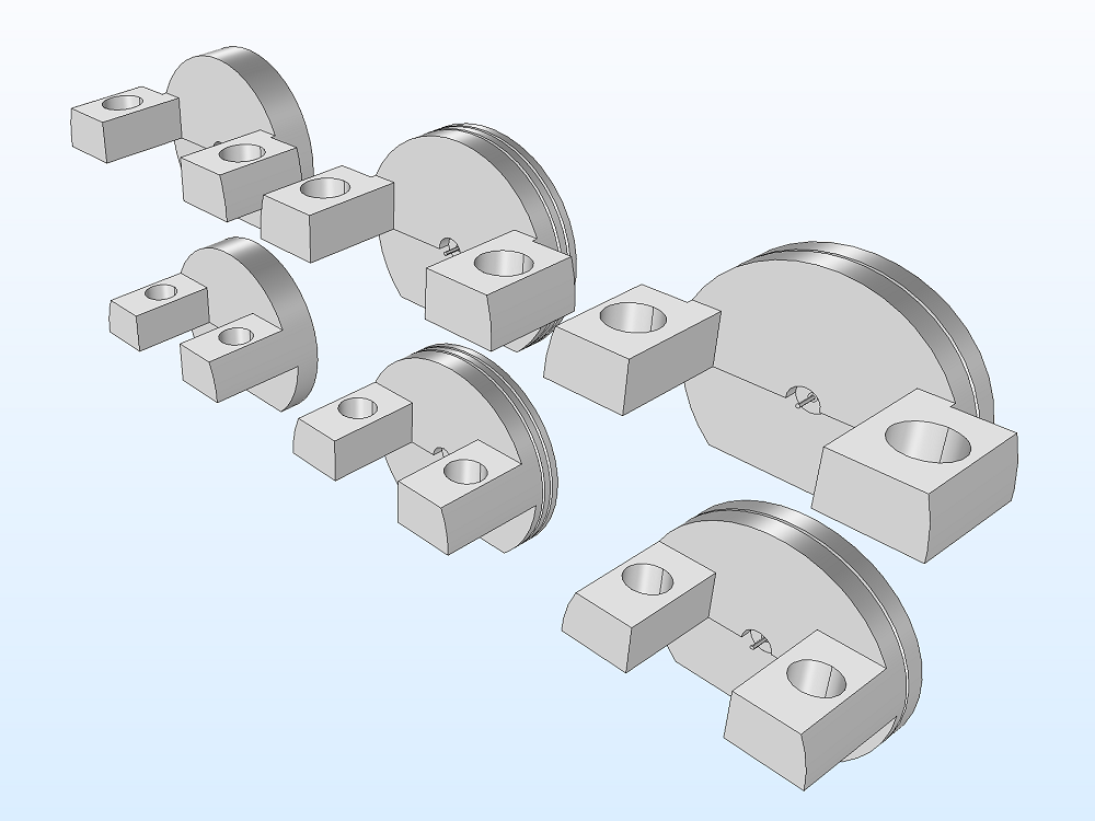
A variety of edge launch connectors in the RF Module Part Library. They are characterized by the highest application frequency and mechanical profile.
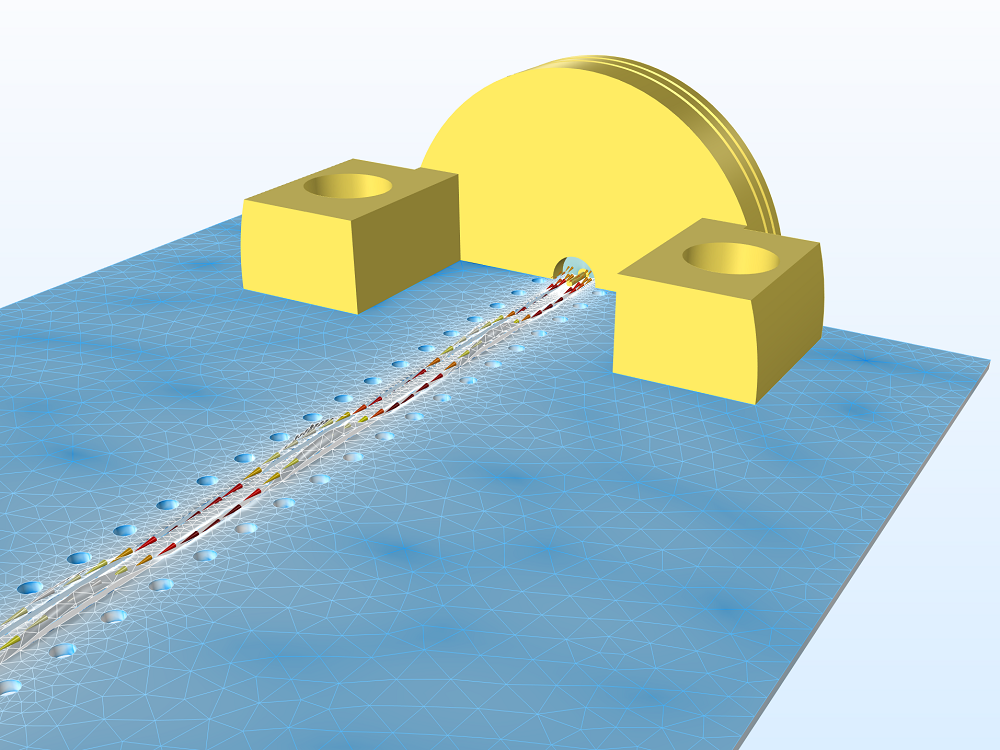
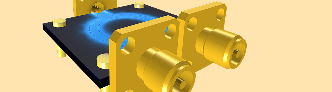
An edge launch connector on a grounded coplanar waveguide (GCPW). A dB-scaled electric field norm and power flow arrows are plotted with color variation according to the phase values.
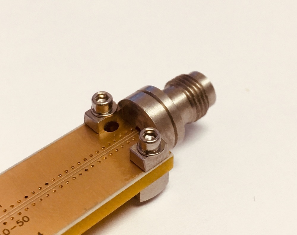
An edge launch connector on a GCPW test board for design verification.
The edge launch connectors in the Part Library are supplied by Signal Microwave, and the design is modified to exclude the screw part that gives mechanical complexity and does not contribute to the electromagnetics simulation. Since these are commercially available products, the geometries are not parameterized.
Next Steps
A tedious design task during computational modeling, such as repeatedly setting up identical geometry sequences, can be simplified by utilizing the RF Module Part Library. Use these parts in your numerical models, check out the part libraries used in other modules, and try creating parts and adding user-defined part libraries.
Additional Resources
- Check out these related tutorial models:
- Read a blog post on simulating an SMA connector on a GCPW


Comments (0)