

An RF MEMS switch is an electromechanical component found in RF systems. It usually consists of a micromechanical bridge or cantilever, a substrate, and an electrode or dielectric layer. These devices can switch at RF frequencies and tend to have high isolation, i.e. power loss when the switch turns off; low insertion loss (loss of signal power when the switch is on), and extremely low (almost zero!) power consumption. Let’s take a look at how you can use COMSOL Multiphysics to simulate an RF MEMS switch.
Analyzing Capacitance and Contact Forces
The RF MEMS Switch model, available in the COMSOL Model Gallery, shows how to simulate and analyze the contact forces and capacitance changes that occur during operation of the switch. The switch geometry contains a thin micromechanical bridge made of a square plate of polysilicon. The plate is suspended 0.9 µm above a silicon nitride film that is 0.1 µm thick. Underneath the film is a grounded counter-electrode.
The main goal of this simulation is to approximate the time it takes the bridge to make contact with the film, and to compute the capacitance of the switch when the bridge is fully pulled in. The COMSOL geometry contains the plate, including the flexures (fixed tabs at the corners that anchor it), and the nitride film is modeled using a function that varies the dielectric constant across the gap between the bridge and the film. As the bridge presses into the film, the mesh — which is used to model the gap — compresses into the nitride layer.
Since the switch is symmetrical, it’s only necessary to model one quadrant of the geometry:

Geometry of the RF MEMS switch as modeled in COMSOL Multiphysics together
with the MEMS Module.
In a switch like this, the bridge responds to an applied electric potential and voltage by pulling down on the film. As the voltage increases, the bridge bends closer and closer to the film, causing the capacitance of the device to increase dramatically. We simulate the contact between the bridge and the film using a technique called the penalty method — a solving algorithm that helps describe the forces occurring in the system.
RF MEMS Switch Model
We want to understand how the bridge bends as it closes the gap, and to know its capacitance in the two configurations. The figure below shows a schematic of the switch operation and the model geometry in the “off” and “on” states.
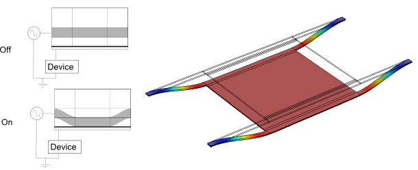
Left, schematic showing the switch operation; right, displacement of the switch when pulled in (color)
as well as the original position of the switch in the off state (wireframe).
The switch is placed between the device and an AC source. When the switch is off (top left in the figure above), its small capacitance appears like an open circuit to the AC signal. When a DC voltage is applied in addition to the AC voltage, the silicon is pulled down onto the isolating nitride film and the switch turns on (bottom left in the figure above). In this configuration, the capacitance is much larger and the switch appears like a closed circuit to the AC signal.
We can model the surface of the nitride film as a nonlinear spring — where the “stiffness” is low when there is no contact between the bridge and the film, but increases as the bridge moves closer to the film and the gap narrows. Knowing, or closely estimating, this spring constant makes it possible to calculate the voltage that causes the bridge to pull in and contact the film; this is called the pull-in voltage.
Here’s what happens to the capacitance as the bridge nears the film:
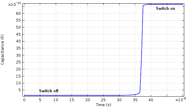
Plot of the capacitance of the switch over time, changing with the increase in voltage.
It remains fairly constant for the first 30 microseconds and then makes a sudden jump. At this point, most of the bridge is in contact with the film. The displacement here is 0.9 µm, so the bridge has fully closed the gap between them. At roughly the same time as this notable increase in capacitance, the displacement makes a similar leap:
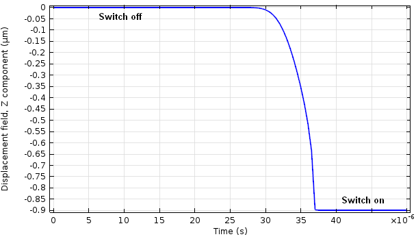
Plot of the displacement over time.
It turns out that the capacitance changes more rapidly than the displacement, because of the non-uniform dielectric constant in the gap.
Further Reading
- Download the RF MEMS Switch model and step-by-step instructions for performing this simulation from the Model Gallery.


Comments (12)
Subhabrata Nath
July 22, 2015I am finding domains only till 20 in the explicit section. I followed all the steps but I am unable to find 23,26,29.
Nakul Haridas
February 12, 2016Hello,
I am trying to see if you can setup the model to do a lift-off case. Going from Off-to On case. Would be grateful if you can provide a solution.
Thanks
Nakul
ha na
November 8, 2017Hi there,
can anyone here has an idea of creating rough surface on the bridge.?
Thanks
Valerio Marra
November 8, 2017Hello,
I suggest contacting support@comsol.com.
Best regards,
Valerio
Rakshith B
February 21, 2019Can you please give the steps to simulate the above switch that shows the movement of the beam?
Brianne Christopher
February 21, 2019 COMSOL EmployeeHi Rakshith,
You can access the MPH-file and documentation for the RF MEMS switch here: https://www.comsol.com/model/pull-in-of-an-rf-mems-switch-16379
Rakshith B
February 23, 2019Hi Brianne
Thank You for the reply, but the displacement animation feature is not possible in the given documentation. Is it possible for us to connect and chat personally for more insight into this as it is a project i am working on.
Hope you oblige
Brianne Christopher
February 25, 2019 COMSOL EmployeeHi Rakshith,
Of course! Please contact our Support team. They will be able to help you out with this.
Online Support Center: https://www.comsol.com/support
Email: support@comsol.com
Best,
Brianne
Rakshith B
April 9, 2019how is the spring stiffness calculated as 1e15 N/m^3 in the global parameters section?
what is the formula used to calculate the spring stiffness?
Rakshith B
April 16, 2019how is the spring stiffness calculated as 1e15 N/m^3 in the global parameters section?
what is the formula used to calculate the spring stiffness?
Bahi Bakeer
November 28, 2020How can I simulate RF MEMS switch stated in this blog using Shell model instead of Solid model?
RAJ KUMARI
April 25, 2021I am new to this tool and have just started to work on RF-MEMS shunt capacitive switches. I have gone through the above switch model and done it but when i want to work on my own design I stuck at meshing part and not able to understand the errors. Is there any type of basic training course on RF-MEMS Switches specifically so that we will be familier with the tool and its basics.