
We often get requests of the type “I would like to just enter my measured stress-strain curve directly into COMSOL Multiphysics”. In this new blog series, we will take a detailed look at how you can process and interpret material data from tests. We will also explain why it is not a good idea to just enter a simple stress-strain curve as input.
Different Material Models
All material models are mathematical approximations of a true physical behavior. Material models can, however, not always be derived from physical principles, like mass conservation or equations of equilibrium. They are by nature phenomenological and based on measurements. The laws of physics will, however, enforce limits on the mathematical structure of material models and the possible values of material properties.
It is well known, even from everyday life, that different materials exhibit completely different behavior. A material can be very brittle, like glass, or very elastic, like rubber. Choosing a material model is not only determined by the material as such, but also by the operating conditions. If you immerse a piece of rubber into liquid nitrogen, it will become as brittle as glass — a popular educational experiment. Also, if you heat up glass, it will start to creep and show viscoelastic behavior.
When analyzing structural mechanics behavior in COMSOL Multiphysics, you can choose between about 50 built-in material models, many of them featuring several options for their settings. You can also set up and define your own material models, or combine several of the material models to, for example, describe a material exhibiting both creep and plasticity at the same time.
Some of the available classes of materials are:
- Linear elastic
- Hyperelastic
- Nonlinear elastic
- Plasticity
- Creep
- Concrete
Without going into details about how you should actually come to the correct decision about an appropriate material model, here are some questions you should ask yourself before you start modeling:
- How large are the stress and strain ranges?
- Will the loading speed be important?
- What is the operating temperature and will it be constant?
- Is there a predefined material model targeted specifically at my material, such as concrete or soil plasticity?
- Is the load constant, monotonously increasing, or cyclic?
- Is the stress state predominantly uniaxial or is it fully three-dimensional?
Based on these considerations, you can then make a choice of a suitable material model. Determining the correct parameters to use in this material model will then be more or less difficult.
On one end of the spectrum, there are common materials (such as steel at room temperature) where many engineers know the material data by heart (E = 210 GPa, ν = 0.3, ρ = 7850 kg/m3) and where data is easily found in the literature or through a simple web search.
On the other end of the spectrum, finding the high temperature creep data for a cast iron to be used in an exhaust manifold can be a major project in itself. Many tests at different load levels and at different temperatures are required. A complete test program for this may take half a year and have a price tag of several hundred thousand dollars.
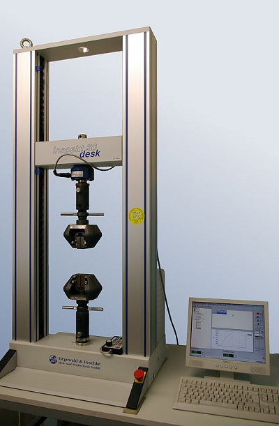
Tensile testing equipment. “Inspekt desk 50kN IMGP8563” by Smial. Original uploader was Smial at de.wikipedia — Transferred from de.wikipedia; transferred to Commons by User: Smial using CommonsHelper. (Original text: eigenes Foto). Licensed under CC BY-SA 2.0 de via Wikimedia Commons.
Common Types of Tests
Before starting your simulation with COMSOL Multiphysics, it is not enough to import the geometry of the specimen, select the material model, and apply the loads and other boundary conditions; you should also provide the parameters for the chosen material model in the operating stress-strain and temperature range. These parameters are typically obtained from one or more tests.
Uniaxial Tension
The most fundamental test is the uniaxial tensile test. This is also what most engineers in daily life refer to when they state that they have a “Stress-Strain curve.” If you look at the list of questions above, it is evident that even this seemingly simple test can leave many loose ends:
- A material may exhibit time dependence even at constant loads, giving creep or viscoelastic effects. Many tests, often at different temperature and stress levels, are needed to give reliable data.
- Material parameters obtained from an ordinary tensile test at low speed may not be representative of the material behavior at high strain rates. A crash analysis might show strain rates as high as 10 s-1, while conventional uniaxial testing machines can use strain rates as low as 10-3 s-1.
- Is the material isotropic or would tests in several directions be required?
- If you only have a tension test, what would happen in compression? With a single curve, you cannot really tell.
- A tensile test will supply stress versus strain in the tested direction, but it will not always contain data about the deformations in the transverse direction. Without that data, you have no information at all about the cross-coupling between the directions in the 3D case.
- When curve fitting experimental measurements, perhaps not all data should be given equal weight. It may so be that the response in a certain strain range has a larger impact on your simulation results.
Uniaxial Compression
Some materials, like concrete, have little or no capacity to carry loads in tension. Here, the uniaxial compression test is the most fundamental test. It has many properties in common with the tensile test.
Other materials, like steel and rubber, can also be tested in compression. It is actually a good idea to do so, as we will demonstrate later in this blog post.
When using only uniaxial testing (whether it is in tension, compression, or both), you can however not achieve the full picture of the properties of a given material. You will need to combine it with some other assumptions like isotropy or incompressibility. For many materials, such assumptions are well justified by experience, though.
We have illustrated how the range of a test will affect your conception of the material behavior in the animation below.
- If you just do the onloading part, it is not possible to discriminate between elastic and plastic behavior.
- By unloading, you can distinguish plastic from elastic behavior, but until the specimen is in a state of significant compression, it is not possible to determine whether an isotropic or a kinematic hardening model would give the best representation.
Biaxial Tension
It is significantly more difficult to design testing equipment that can create a homogenous biaxial stress state. Biaxial testing is often used for materials that are available only in thin sheets, like fabrics, for instance. By controlling the ratio between the loads in two perpendicular directions, it is possible to extract much more information than from a uniaxial test.
Triaxial Compression
For soils, which generally need to be confined, triaxial compression is a common test. Triaxial compression tests could in principle be applied to a block of any material, but the testing equipment is difficult to design. The low compressibility of most solid materials also makes triaxial testing less attractive, since the measured displacements will be small when the material is compressed in all directions.
The Triaxial Test model shows a finite element model of a triaxial compression test.
Torsion
The torsion test, where a cylindrical test specimen is twisted, is a rather simple test that generates a non-uniaxial stress state. The stress state is, however, not homogenous through the rod. Therefore, some extra processing is needed to translate the moment versus angle results to stress-strain results.
Testing Hyperelastic Materials
In an upcoming blog post in this series, we will make an in-depth demonstration of how to fit measured data to a number of different hyperelastic material models. In the example here, we will assume that you have been able to fit your data to the tests. The raw data consists of two measurements: one in uniaxial tension and another in equibiaxial tension, as shown below.
The nominal stress (force divided by original area) is plotted against stretch (current length divided by original length).
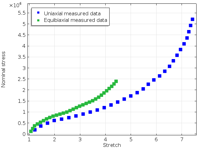
Measured stress-strain curves by Treloar.
Since the data covers a wide range of stretches, the experimental results are clearly nonlinear. The simplest hyperelastic models with one or two parameters will probably not be sufficient to fit the experimental data. The Ogden model with three terms is a popular model for rubber, and it is the model we used here.
A least squares fit will give the results below when assigning equal weights to both data sets. As we can see in the graph, it is possible to fit both experiments very well with a single set of material parameters.
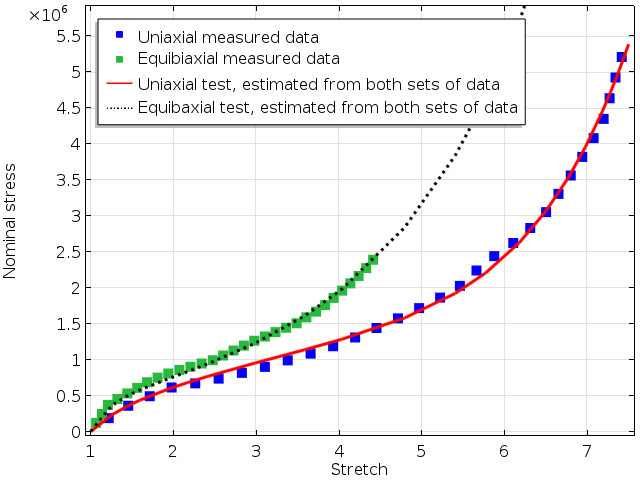
Fitted material parameters using a three terms Ogden model.
But what if the biaxial test had not been available? Fitting only the uniaxial data will give a different set of material parameters, which will of course fit that set of experimental data even more closely, but it would deviate from the biaxial results. This is shown below.
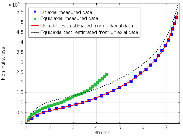
Analytical results for uniaxial and biaxial tension when only the uniaxial data was used to fit the model parameters.
Clearly, the prediction for a equibiaxial stress state will differ between the two sets of parameters. As we can see, the error in stress in the biaxial curve is more than 20% at some stretch levels.
What about other stress states? Two stress states that can be simulated in a simple finite element model are uniaxial compression and pure torsion. The uniaxial stress-strain curve over a wide range of stretches is shown below. The results on the tensile side are not as sensitive to the data set used for obtaining the material parameters as the compressive side is. This is not surprising as tensile data is used for parameter fitting in both cases, whereas neither of the experiments contain any information about the compressive behavior.
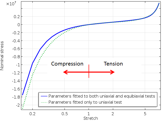
Uniaxial response ranging from compression to tension. The scale on the x-axis is logarithmic.
Note that operating conditions of rubber parts, such as seals, are often under predominantly compressive states. If the data sets used for parameter fitting contain only tension data, this may be a source of inaccuracy when modeling multiaxial stress states.
Finally, let’s have a look at a simulation where a circular bar is twisted. The same type of discrepancies between the results from two sets of material parameters as above can be seen below.
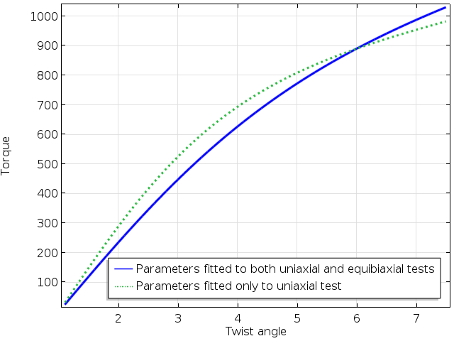
Computed torque as function of the twist angle.
Finally, it should be noted that many hyperelastic models are only conditionally stable. This means that even though the estimated material parameters are perfectly valid for a certain strain range, a unique and continuous stress-strain relation may not even exist for other strain combinations. We often come across such problems in support cases. This is unfortunately rather difficult to detect a priori, since it would require a full search of all possible strain combinations.
Concluding Remarks and Next Up
Measured data must be processed and analyzed before being used as input for simulations. For material models other than the simpler linear elastic model, it is a good idea to make small examples with a unit cube to assess the behavior under different loading states before using the material model in a large-scale simulation.
So the answer to the question: “I would like to just enter my measured stress-strain curve directly into COMSOL Multiphysics” is that such an approach is not recommended. That would make the software a black box where the user really must take a number of active decisions in order to obtain meaningful results.
Up next in our Structural Materials series: We will discuss nonlinear elasticity and plasticity.


Comments (0)