The Usage of Form Union and Form Assembly
The Geometry branch in the Model Builder tree consists of a sequence of geometry operations. This can include sketches, geometric primitives, imported CAD files, Boolean operations, etc., that can be used to create the geometry that you want to model. At the end of this sequence, there is a Form Union node, and you have the option to change this to Form Assembly. This choice of method influences how the final geometric model used for the physics settings and meshing is generated. In this article, we will describe the differences between the methods and when to switch between them.
Tutorial Video: The Form Union and Form Assembly Geometry Finalization Methods
Further Details and Differences
The Form Union and Form Assembly methods unite the geometric objects in your model to form a single object. However, the way the collection of domains in your model is treated differs. Here, we elaborate on some of these distinctions outlined in the tutorial video above and also discuss other factors not covered in the video.
What are domains? See our Learning Center article on geometry concepts and nomenclature to learn more.
Form Union
Form Union is the default finalization method for generating the geometric model for the physics. It is equivalent to taking a Boolean union of all objects in the geometry sequence and keeping the interior boundaries — that is, a single geometry object is created and composed of many different domains. Any overlapping geometry objects will become a single object composed of different domains for each enclosed volume. This is illustrated in the image below, where three blocks of different sizes overlap in space. The result of using the Form Union operation is shown below, with the different resulting domains in different colors. To see this in the software, you can download the block geometry MPH-file attached to this article. You can display geometry labels and open the Selection List window to further clarify the domains resulting from the Form Union operation.
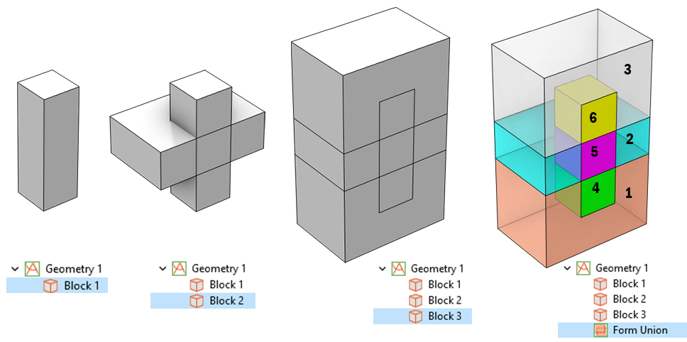
The sequence of operations used to compose a geometry of three blocks (first three figures) is finalized using Form Union. The different domains resulting from this finalization are displayed in the rightmost figure.
When the geometry is finalized using Form Union, the resulting mesh will be connected and conforming. That is, the mesh elements on either side of an interior boundary will share the same nodes, edges, and faces. The interior boundaries are meshed, and you can apply different element sizes to different domains, as shown in the image below.
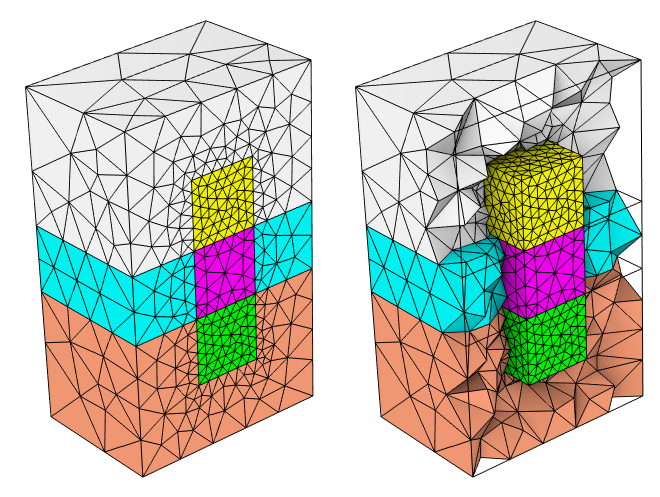
Different element sizes are applied to some of the resulting domains of the geometry. The mesh is conforming and connected at all interior boundaries regardless of the differences in element size.
In the physics settings, each of these different domains can have different material properties. By default, continuity of the fields and the fluxes will be maintained across the interior boundaries, and it is possible to add a variety of different discontinuity or jump conditions at interior boundaries for the various physics.
Having a mesh that is conforming is required for all of the electromagnetic interfaces that are solving for (as dependent variables) two or three components of either the magnetic vector potential, the electric field, or the magnetic field. Such interfaces require the mesh elements to be conforming at all boundaries.
The physical implication of the Form Union step is that the domains in the model cannot slide or move relative to each other. This is due to the fact that the Form Union operation will form one interior boundary, between two domains, for each pair of touching boundaries, such that the resulting mesh will be connected (and conforming) across the interior boundary. This is an appropriate default assumption for most modeling scenarios when working in COMSOL Multiphysics®, but it is not valid when movement of adjacent objects is needed. For such cases, or when you want to have a nonconforming mesh between adjacent domains, change Form Union to Form Assembly.
Form Assembly
Form Assembly differs from Form Union in that it does not compute a Boolean union of the geometry objects. Instead, it collects them into an assembly object. After implementing the Form Assembly operation, adjacent objects will become disconnected domains and movement is possible if needed. Because of this, you need to switch to Form Assembly for the following physics interfaces when you have touching objects in your geometry sequence:
- Solid Mechanics interface, when Contact features are included
- Multibody Dynamics interface
- Rotating Machinery, Magnetic interface
- Rotating Machinery, Fluid Flow interfaces
Since Form Assembly does not compute the Boolean union of the objects, you cannot use Form Assembly to generate domains for the overlapping regions between objects. The number of domains in the geometry will not change as a consequence of the Form Assembly operation. The adjacent objects of the torus and the block in the figure below become two disconnected domains after using Form Assembly. To see this in the software, you can download and open the torus block MPH-file attached to this article.
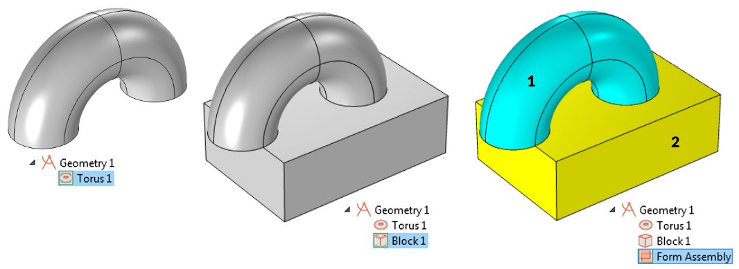
The sequence of operations used to compose a geometry of a torus and block (left and center) is finalized using Form Assembly. The different domains resulting from this finalization are displayed in the rightmost figure.
The Form Assembly operation will identify the touching boundaries of all objects and by default will form so-called Identity pairs or Contact pairs out of them. The default behavior is to create these pairs automatically, although they can also be set up manually. Both types of pairs can also be generated with the option to create imprints, which will project the outline of the faces onto each other. These options are illustrated below for the touching torus and the block, with the faces that compose the pairs highlighted in the exploded views.
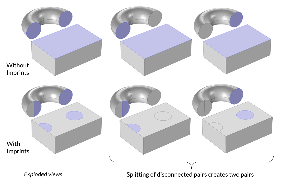
Exploded view of an assembly without imprints (top) and with imprints (bottom).
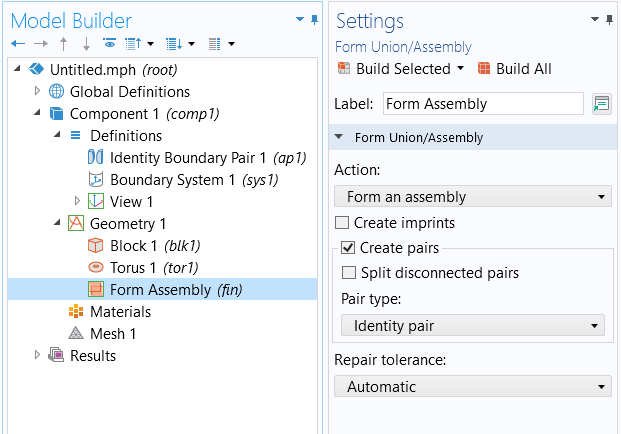
The Settings window for the Form Assembly node.
By default, a single pair defining the mating faces will be created for all touching faces between two domains, even if these faces are nonadjacent within each domain. It is possible to override this behavior by choosing the Split disconnected pairs check box so that one pair is created for each mating face pair, as shown in the figure featuring the exploded views.
The choice between creating an Identity pair and a Contact pair is governed by the physics that you want to solve. Creating Contact pairs should only be done when solving a structural mechanics problem with Contact features. This means that faces can come in and out of contact and can slide relative to each other, and forces and fluxes will be transferred between the faces only when they are in contact.
When using any of the Rotating Machinery interfaces, the option to form identity pairs, without imprints and without the splitting of disconnected pairs, is the appropriate choice. It is also possible to choose to create no pairs at all, and this can be useful when solving a multibody dynamics problem.
Automatically generated boundary pairs can be disabled, and you can also change the type of pair, which can be useful if, for example, you are applying Contact features only in some locations of your geometry. Alternatively, you can use Boolean Union operations in the geometry sequence to unite some of the objects, and then you can use Form Assembly to generate contact pairs for the mating faces between the remaining objects.
The Form Assembly functionality is also helpful if you want to have a disconnected mesh across interior boundaries, which we detail further in the section below.
Meshing After Form Assembly
The mesh created when using Form Assembly is not connected across the two sides of a boundary pair, and thus the mesh is nonconforming between disconnected domains. The mesh elements on the mating faces do not share node points, nor edges, nor faces. The mesh can either be matching or nonmatching on the mating faces, depending on how it is created. With imprints enabled, the mating faces of the pairs will get the exact same shape, although the mesh of the two mating faces is not connected and can be nonmatching. When using this option, you can create matching meshes on the mating faces by:
- Using the Identical Mesh attribute, as demonstrated in the animation below.
- Using the Copy Face operation. First, create a mesh for one side of the pair, and then use Copy Face to copy the mesh to the other side. Such a mesh is shown below in the rightmost figures. To learn more, refer to the MPH-file for the torus and block geometry (attached here).
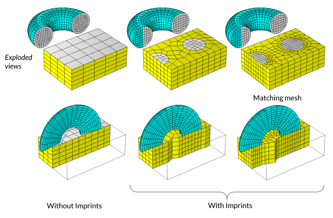
Form Assembly is used to finalize a geometry consisting of part of a torus and a block. The exploded views display the differences in a nonmatching and matching mesh for the geometry.
The continuity of the fields or the fluxes across a boundary pair in the case of using Form Assembly is enforced by having Continuity boundary conditions applied for the physics. (See examples by opening "File-> Application Libraries" in COMSOL Multiphysics and searching @tag:cont and @tag:dcont.) In most cases, the Continuity boundary condition will be applied by default for each Identity pair and physics interface in your model. Discontinuity or jump conditions can also be applied. The Continuity boundary condition will approximately enforce continuity of the fields and fluxes across a pair. In contrast, the mesh after Form Union is conforming across interior boundaries, and thus the continuity of the fields and fluxes is naturally satisfied via the finite element method. Results obtained with a nonconforming mesh are less accurate than results obtained with a conforming mesh, and results from a nonmatching mesh are less accurate than those from a matching mesh and become increasingly less accurate as the relative element sizes across the pair differ. Thus, the mesh after Form Union will give the most accurate results but will require the most memory to solve, and a nonmatching mesh after Form Assembly without imprints will be the least accurate and will use relatively less memory to solve.
Switching to Form Assembly may be helpful if you want to reduce the number of elements in the mesh, and thereby the memory required for solving. It is recommended that you investigate using nonconforming meshes for problems involving thermal and structural analyses. Such models can often consist of geometry objects that may have different feature sizes, and hence different mesh element sizes. When using the Form Assembly method to generate the geometric model for physics and meshing, these cases are likely to show the greatest benefit in terms of using less memory while still giving good accuracy.
Use Cases for Form Assembly
As noted earlier, there are certain modeling scenarios where you should switch from the default Form Union geometry finalization method to Form Assembly, such as when using Rotating Machinery interfaces or when working with contact or multibody dynamics simulations. This feature makes it possible to more effectively mesh model geometry, such as for large CAD assemblies as well as for complex PCB and chip designs. Learn more about some of these Form Assembly use cases by checking out the resources linked below:
- Multibody dynamics: enabling motion in a spring-loaded centrifugal governor (video)
- Contact simulation: creating contact pairs for structural contact modeling (video)
- Rotating machinery: particle tracing in a micromixer (video)
- Complex circuit board and chip designs: thermomechanical analysis of a surface resistor (model PDF)
- Time explicit applications: resolving wave propagation (blog post – see the Meshing and Solving section)
Submit feedback about this page or contact support here.