

“It’s time to move!” the smartwatch notifies the wearer who has been sitting still for too long. “Ping!” says the cellphone with a notification on its screen. “Make a U-turn at the next traffic light,” the GPS calls out to the driver moving in the wrong direction. These are familiar alerts nowadays, and with the growing demand for sub-GHz, 5G, and wearable devices, they are expected to become even more prevalent. At the same time, companies are expected to deliver more integrated functionality; low-power, low-cost devices; small form factor; and ever-increasing data rates. The solution calls for better RF filters and thereby better resonators, but there’s more to the story.
Everything Around Us Needs an RF Filter
In a keynote talk from COMSOL Day: Electronic Devices, Bichoy Bahr of Texas Instruments discussed the ever-growing demand for sub-gigahertz (sub-GHz) technologies, which are now being used by the billions for home and industrial automation, infrastructure monitoring, wearables, smart agriculture and fishing, and so on. RF filters, which are made up of one or many resonators, play a critical role in the function of these devices.
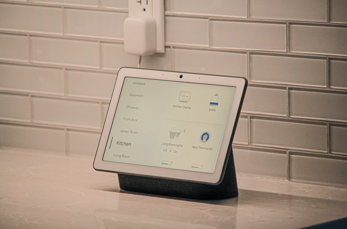
A smart display for home automation. Photo by James Yarema on Unsplash.
During his talk, Bichoy Bahr said that this “pushes the burden to basically have better resonators and better RF filters […] in general.” He went on to explain that now resonators must have a small, compact form factor; good stability; low cost; and low power. However, creating a resonator that meets all of these design requirements is challenging. “MEMS resonators actually provide a good solution for these challenges,” said Bahr.
MEMS Resonators Bring Advantages, But Are Not Without Challenges
The very small size, high-quality factor (high Q), and small footprint of MEMS resonators is what makes them a suitable choice for keeping up with the fast-paced automation industry. They can also be integrated into complementary metal–oxide–semiconductors (CMOS), all while maintaining their high Q. Other benefits of MEMS resonators include how they allow frequency tuning and can be used to create large arrays, which can help when designing filters for different protocols or different frequency standards.
On the flip side, MEMS resonators also have their fair share of drawbacks that can make them difficult to manufacture and use. For example, a lot of them employ a release structure with gaps, which can cause them to have yield issues. They can also be sensitive to packaging and stress and can have temperature stability issues. Lastly, the integration of MEMS resonators with CMOS technology isn’t easy, which is something Bahr focused on in his keynote presentation.
CMOS–MEMS Integration
There are several approaches that can be used to integrate CMOS and MEMS technology. The earliest known approach is called MEMS first, where the MEMS is manufactured before the CMOS technology on a wafer. This can be used for devices like accelerometers. Other approaches include CMOS–MEMS, MEMS last, and MEMS in package (the approach we see most often today).
Dream or Reality?
According to Bahr, the dream approach for integrating these two technologies would be to create MEMS resonators that are encapsulated within the CMOS die itself. With this approach, which Bahr calls the front-end-of-line (FEOL) MEMS–CMOS, resonators would be fabricated just like any other transistor or circuit and wouldn’t require extra postprocessing steps and special vacuum packaging. Such resonators would be fully protected; allow access to the FEOL materials; and would be without air gaps, free surfaces, parasitics, and wire bonds.
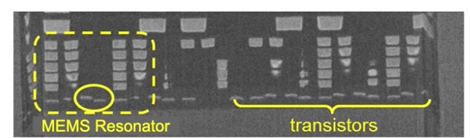
A representation of a MEMS resonator encapsulated in a CMOS die and typical transistors.
Bond wires on a chip.
“It is a very optimistic view of MEMS to be able to achieve this,” said Bahr. However, developing FEOL MEMS–CMOS resonators would be challenging due to acoustic confinement, transduction, and packaging stress. To study the intricate structure and operating principles of this new class of resonators, Bahr incorporates multiphysics modeling and simulation into his research.
Getting Closer: PnC Waveguide Design
Bahr analyzed a FEOL MEMS–CMOS resonator that incorporates a phononic crystal (PnC) waveguide design. This design is both periodic and able to control the flow of sound or mechanical vibration. According to Bahr, the COMSOL Multiphysics® software was crucial to understanding the vertical and horizontal confinement of the PnC waveguide and thereby helped in enhancing the design. Bahr also shared how the design they developed was then manufactured in IBM 32 nanometer SOI technology.
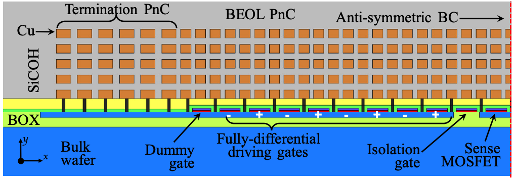
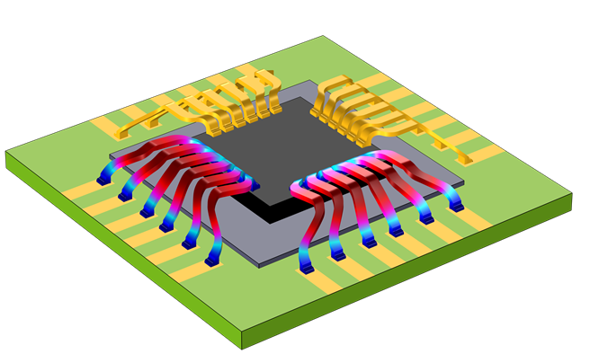
A model of the FEOL MEMS–CMOS resonator in IBM 32 nanometer SOI technology.
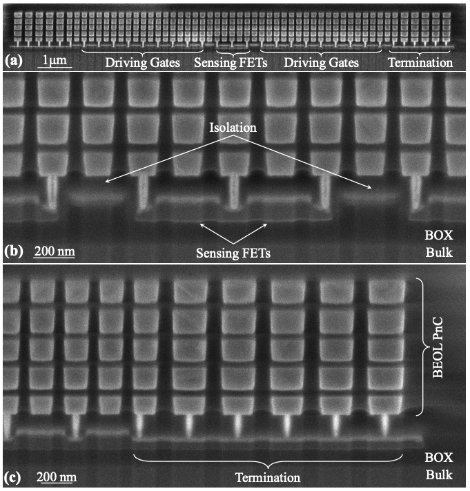
A scanning electron micrograph (SEM) image of the unreleased manufactured structure.
Upon looking at the design’s RF characterization results, Bahr found that it still needed to be enhanced. “The [frequency-response] measurement we got had a very high Q, but it didn’t look great. It was very noisy and had a lot of peaks,” said Bahr. Looking into the results further, he confirmed that the concept for the design was still good, but its transduction was very weak and it couldn’t be used for practical applications. “That had us looking elsewhere for better transduction.”
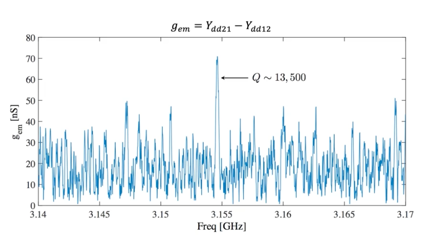
Measured frequency response.
The Final Design: Ferroelectric Resonators in CMOS
Through research, Bahr and his team found a diagram like the one below, which is sometimes used for CMOS technology. With this new knowledge, they decided to try using ferroelectric materials, which are also pieozelectric, for their resonator’s transduction.
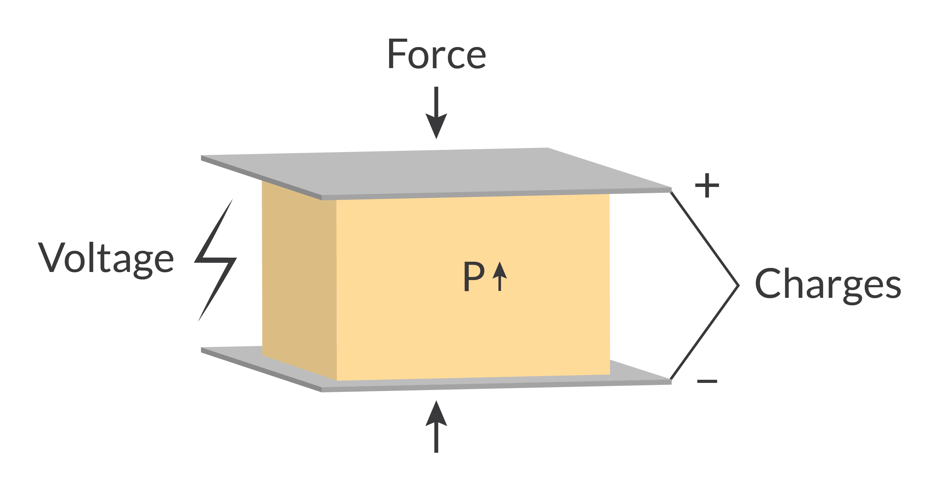
A schematic of the piezolectric transduction technique.
After simulating and analyzing this new resonator design, the team went on to fabricate the device and measure it. With the new design, they found that it had a frequency of 701 MHz, a quality factor of 781, and a strong resonance due to the piezoelectric transduction. The transduction can also be made stronger or weaker, or it can even be completely turned off. This would be especially helpful for programmable or tunable filters and resonators. At the end of his talk, Bahr said that ferroelectrics are yielding promising results and could be used for meeting today’s highly demanding standards for CMOS–MEMS technology.
Next Step
Watch the video to learn more about CMOS–MEMS resonators and how simulation is being used at Texas Instruments for this technology.
References
- B. Bahr, R. Marathe, and D. Weinstein, “Theory and Design of Phononic Crystals for Unreleased CMOS-MEMS Resonant Body Transistors,” Journal of Microelectromechanical Systems, vol. 24, no. 5, pp. 1520–1533, 2015; https://ieeexplore.ieee.org/abstract/document/7096929
- Y. He et al., “A tunable ferroelectric based unreleased RF resonator,” Microsyst Nanoeng, vol. 6, p. 1–7, 2020; https://doi.org/10.1038/s41378-019-0110-1
- Y. He , B. Bahr, and D. Weinstein, “A Ferroelectric Capacitor (FeCAP) Based Unreleased Resonator,” Transducer Research Foundation, 2018; https://transducer-research-foundation.org/technical_digests/HiltonHead_2018/hh2018_0071.pdf

Comments (0)