How to deal with penetration when modeling indentation test?
Posted Nov 24, 2023, 11:18 p.m. EST General, Structural Mechanics 4 Replies

Please login with a confirmed email address before reporting spam
Hi,
I am working on the modeling of a elastic homogeous material indented by a rigid indenter, spherical or conical.
The indenter is model by rigid material, and the contact is defined through contact pair. The indenter and the elastic material is put together through 'form assembly'. The 'segregated augmented Lagrangian' method is employed, with preset penalty factor control tunned for speed. The prescribed displacement increases cubically (the model file of an isotropic elastic trail run is attached)
However, severe penetration occurs slightly away from the indenter tip (see the attached figure).
I have beening reading related threads in this forum, and tried
1)select the same boundaries as both source and destination in a contact pair as posted by @Henri in this thread. I switch the source and destination of a contact pair (p1) and define a new one (p2). Both p1 and p2 are selected as pairs in the definition of 'contact'. This causes error 'Rigid domain adjacent to contact destination boundary'.
2)reduce the increase step path. The step number is increased from 100 to 1000.
3)refine the mesh. I have tried to refine either side of the contact pair.
4)increase the scale factor of contact pressure as described by an example 'models.sme.cylinder_roller_contact' and mentioned by @John in this post. I increased this factor from the default 1e8 to 1e14. Only the error of lumped step decreases, but penetration still occurred.
I would really appreciate it if someone could shed light on this.
Best,
HC Liu
Attachments:

Please login with a confirmed email address before reporting spam
First some comments to what you have tried:
- Is used when there is a risk of self-contact, that is a certain boundary comes into contact with itself. This is not the case here. The error is caused by the fact that it is required that at least one of the two contacting objects is elastic (and this should be the 'destination' side).
- Can be used if there is divergence in the iterations. Else, it should not be needed.
- Can be a good idea. In particular, you want to resolve the curvature of the indentor.
- Doing that is catastrophic. It essentially means that you remove all convergence checks on the contact pressure. The scale factor should be of the same order as the expected contact pressure. The default 1E8 (=100 MPa) is characteristic for steel-to-steel contact.
The augmented Lagrangion method that you are using is 'exact' in the sense that there will be no overlap for a converged solution. What you need to do is to make sure that you get more iterations. You can either decrease the solver tolerance or the scalings of the degrees of freedom.
Note that the 'penalty factor' in the Contact settings strongly affects the convergence rate of the contact iterations. It also affects the estimate of the error. A low penalty factor will give meany iterations, and also a risk that the convergence criteria look fulfilled while there is still an overlap.
Another hint: Using a rigid domain / rigid material for the indentor is overkill. You can just use a Prescribed Displacement on that domain.
-------------------Henrik Sönnerlind
COMSOL
Please login with a confirmed email address before reporting spam
First some comments to what you have tried:
Thank you so much @Henrik for your detailed explanation.
Your advice definitely make sense to me. So, I tried to follow it, but failed to get expected results. I am not sure if I did it right. I was wondering if you could give furher more guidance.
About the Comments,
The default 1E8 (=100 MPa) is characteristic for steel-to-steel contact.
Is this true only for the SI unit system or for all unit systems? I mean, does the meaning of this value keep consistant with the unit system?
I am used to reset the 'Unit System' to 'None' like in other FEM softwares. But I keep it in my mind that the unit system is 'mm for length, N for force, t for mass, MPa for pressure, ...'. Under this circumstance, does the default 1E8 represent 100MPa or 1E8 MPa?
(refine the mesh) Can be a good idea. In particular, you want to resolve the curvature of the indentor.
About the mesh refinement, I encountered another problem. Sometimes, I have to refine the mesh. Otherwise, the derived 'indentation modulus v.s. depth' curve isn't smooth.
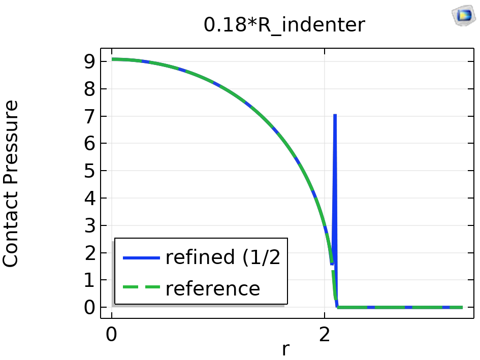
But when the mesh is refined, the distribution of contact pressure becomes bumpy near the contact edge (see the figure below or the attached graph). The contact pressure increases and decreased suddently by a vary large extent. Could you give me a hint about this?
Here are some trail run following your advice.
What you need to do is to make sure that you get more iterations. You can either decrease the solver tolerance or the scalings of the degrees of freedom.
I changed the 'Relative tolerance' from default 0.001 to 0.0001 under the subnode 'Study 5-->Solver Configurations-->Solution5 -->Stationary Solver 1 -->General'. And the 'Maximum number of refinements' from 15 to 30 under '...-->Stationary Solver1 --> Direct-->Error-->Iterative refinement'. The 'Maximum number of iterations' in the setting for 'segregated 1' is also change from 15 to 30.
The calculation time apprximately doubled. I can see from the Convergence Plot that the Error is below 1E-4 now, but the Graphics view still gives a penetration plot and no appreciable change can be observed.
A low penalty factor will give meany iterations, and also a risk that the convergence criteria look fulfilled while there is still an overlap.
I use Segrated Augmented Lagrangian Method. In previous simulation, I used the preset penalty factor control tunned for speed, since the indenter initially touches the structure through no more than 1 point and there is presumably no contact pressure.
I tried to manually tune the penalty factor multipiler. The default 1 makes no difference. So, I changed it to 10 (which is the maximun contact pressure gained from previous simulation). This caused divergence.
How to set the penalty factor control so that better performance than the preset parameters can be achieved? Could you shed more light on this?
Another hint: Using a rigid domain / rigid material for the indentor is overkill. You can just use a Prescribed Displacement on that domain.
I use Prescribed Displacement this time in substitution of the previous Rigid Material to model the rigid indenter. The displacement is prescribed as (u0r,u0z)=(0,-hi*pw1(par)). The solver configurations is reset to default before running the computation.
The deformation plot doesn't change. The penetration still occurs.
I have got loads of questions. Thank you so~ much for your time and patience.
Best, HC Liu
Attachments:
Please login with a confirmed email address before reporting spam
Generally speaking, it is difficult to tell why you see an overlap. I would still suspect that you are looking at an insufficiently converged solution.
Variable scaling: If you switch off the unit handling, you are on your own. I would not do that unless necessary. In your case, the contact pressure scaling should then be in terms of MPa, so 10-100 is probably a good number. This could still be a source of your problem. Also, the displacement scale should then be a relevant number of mm. BTW: There is a built-in unit system with your favorite units: The MPa system.
The bumpy result: This is may be a plotting artifact, but it also possible that there is an unconverged solution. Start by switching off 'Refinement' and 'Smoothing' in the plot so that you can see the raw data. Zoom in on the region with the bump. The contact pressure is represented by a linear shape function over each element.
Penalty factor choice: A too large value will cause divergence. It is not easy to determine an optimal value, but it seems that the defaults are OK for you.
Iterative refinements: If iterative refinements are needed, that may indicate some problem in the physics. Iterative refinements are only needed when the stiffness matrix is ill-conditioned. Double-check boundary conditions and material data.
-------------------Henrik Sönnerlind
COMSOL
Please login with a confirmed email address before reporting spam
Generally speaking, it is difficult to tell why you see an overlap. I would still suspect that you are looking at an insufficiently converged solution.
Thank you @Henrik Sönnerlind for your reply.
I checked the overall results, e.g., the derivated indentation modulus. It matches the prediction of related theories, though there are penetration and bumpy contact pressure.
About the penetration, is it possible that the peneration is also a plotting artifact or that it doesn't matter so much? If so, I can live with that.
To be honest, the distribution of contact pressure concerns me more, because I might need to gain insights about the contact process through it.
Variable scaling: If you switch off the unit handling, you are on your own. I would not do that unless necessary. In your case, the contact pressure scaling should then be in terms of MPa, so 10-100 is probably a good number. This could still be a source of your problem. Also, the displacement scale should then be a relevant number of mm. BTW: There is a built-in unit system with your favorite units: The MPa system.
I'll leave this to the default.
The bumpy result: This is may be a plotting artifact, but it also possible that there is an unconverged solution. Start by switching off 'Refinement' and 'Smoothing' in the plot so that you can see the raw data. Zoom in on the region with the bump. The contact pressure is represented by a linear shape function over each element.
Not sure if I did it right. In the settings of contact pressure (comp1.solid.Tn) Line Graph, I chose No refinement for the Resolution and None for the Smoothing. But the plot dosen't change.
The zoomed in graph is as follows (or see the attached picture)
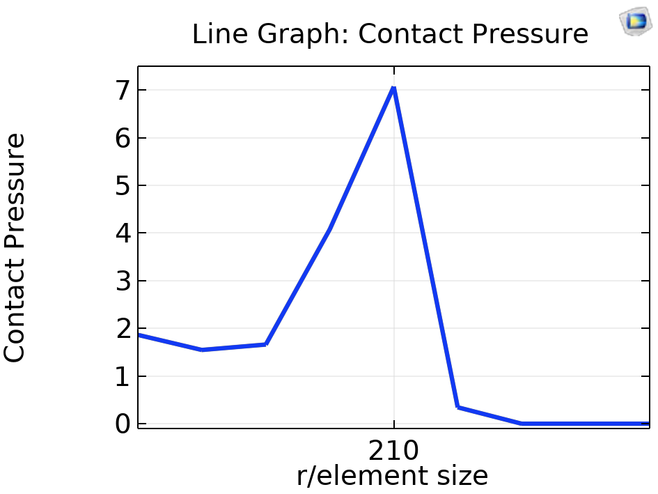
Note: the x-axis is r re-normalized by the element size, which can be regarded as the element id on the contact surface.
Penalty factor choice: A too large value will cause divergence. It is not easy to determine an optimal value, but it seems that the defaults are OK for you.
I understand that the penalty factor is hard to determine a priori without enough experience, so I'll leave this to the default.
Iterative refinements: If iterative refinements are needed, that may indicate some problem in the physics. Iterative refinements are only needed when the stiffness matrix is ill-conditioned. Double-check boundary conditions and material data.
I'll leave this to the default, too.
Thank you again for your detailed comments and explanation.
Best,
HCL
Attachments:
Reply
Please read the discussion forum rules before posting.
Discussion Forum Rules and Guidelines
The goal of COMSOL Access is to provide a forum for you to communicate effectively with COMSOL as well as your colleagues within the multiphysics simulation community. This involves providing you with access to technical support and downloads of the latest {:comsol} software releases, as well as the ability to share your comments and work with other users of the {:comsol} software through forums such as the blog, discussion forum, and Application Exchange. In order to make this an efficient and pleasant experience for you and other members of COMSOL Access, we ask that you follow a few rules and guidelines.
When registering for COMSOL Access, you agree to provide your complete and truthful information for all fields requested on your COMSOL Access account registration page. You also agree to maintain the accuracy of all information associated with you on your COMSOL Access account. You agree to maintain your COMSOL Access account for use solely by you, not to share your username and password with anyone else, and to take appropriate precautions to restrict access to your username and password from others. Furthermore, you agree not to submit any information relating to your employer through your COMSOL Access account without your employer’s authorization. Should you use a COMSOL Access account associated with an employer, you agree to immediately discontinue using that account upon termination of that employment.
The moderators of the forums will remove any generally objectionable material as quickly as possible. You acknowledge that all posts made to these forums express the views and opinions of the author and not the administrators, moderators, or webmaster (except for posts by these people). Hence, they will not be held liable.
You agree not to post or link to any material that is abusive, obscene, vulgar, slanderous, hateful, threatening, sexually oriented, or that infringes upon or violates any third-party rights or any other material that may violate any applicable laws. You agree that you will not otherwise use your COMSOL Access account to violate or to assist anyone in violating any law. Engaging in any activity in violation of these COMSOL Access rules and guidelines may lead to you being immediately and permanently banned from COMSOL Access. The IP address of all posts is recorded to aid in enforcing these conditions. You agree that the webmaster, administrator, and moderators of the forums have the right to remove, move, or close any topic at any time as they see fit. As a user of COMSOL Access, you agree to any information you have entered into any of the forums being stored in a database.
You agree that you will not use your COMSOL Access account in violation of any applicable export control laws. You represent and warrant that you are not subject to any comprehensive sanction or embargo by the U.S. or any other country, nor are you identified on any list maintained by the U.S. government that identifies persons for which the U.S. maintains restrictions. Further, you represent and warrant that you are not subject to any restriction on the receipt of technology or products under the export control laws of the U.S. or any other country.
Basic Rules
- Flaming: Do not post any messages that harass, insult, belittle, threaten, or flame another member or guest. Debates are fine, but argue with the point, not the person.
- Trolling: Do not post with the purpose of starting a dispute. Note that a person disagreeing with your opinion is not considered trolling; keep it civil, even if you are sure that the other person is wrong. Anything seen as trolling will result in you being banned.
- Spamming: Posts without content or containing nonsense waste space and everyone's time. Spam will be removed from the forum.
- Offensive Posts, Links or Images: Do not use profanity, racial, ethnic, religious, or other slurs or any other offensive material.
- Advertising: Posting of advertisements for products or services, links to auctions, affiliate links, links to promote websites, and so forth is not allowed.
- Disclosure of Personal Information: Do not disclose any other member's email, real name, address, phone number, IP address, or other personal information. This includes posting contents of emails and private messages without the sender's consent. Do not bring personal disputes into the forums. Bans and warnings issued to other users are considered personal information.
- Misleading Titles: The subject line of the post should be as informative as possible about the content of the post. This also reduces the amount of duplicate posts.
- Thread Hijacking: Taking a thread off-topic to pursue one's own agenda is not permitted.
- Piracy: Do not upload, post, email, transmit, or otherwise make available any content that infringes upon any patent, trademark, trade secret, copyright, or other proprietary rights ("Rights") of any party. This includes COMSOL model files created by a forged or illegitimate license.
- Honesty: Users must provide truthful information in creating their COMSOL Access account.
These rules are subject to change. The moderators reserve the right to remove, edit, or move posts at their discretion. The COMSOL Access administrators will reserve the right to permanently remove a user account without notice if any of the rules are not followed. Particular services accessible with your COMSOL Access account may be subject to additional rules. You agree to comply with all rules applicable to each service you access through your COMSOL Access account.
Posting Guidelines
When posting, understand that you are trying to communicate with other people. Although many COMSOL Access members are not fluent in English, the official language of this forum is English.
Here are some important guidelines of language:
- Write in English.
- If you are familiar with LaTeX, please use this to write mathematical equations.
- Always do a quick check for spelling/grammar mistakes.
- Format your post in a legible manner. Use the Preview button often.
- Be concise and articulate as much as possible.
- Use the Enter key to create paragraphs.
- Capitalize correctly. It is difficult to read posts that are written entirely in uppercase or lowercase.
- Use correct punctuation. Avoid run-on sentences.
- Try to avoid using “text speak”, “net speak”, or slang. The purpose of language is to be understood.
- Never invent acronyms and use as few acronyms as possible. For example, write "COMSOL Multiphysics" and not "CMP".
- Review your post before publishing it. Try to catch typos.
- Please check to see if a topic has already been posted. Do not post multiple threads on the same topic.
Disclaimer
By submitting content to the forums, you hereby grant COMSOL a nonexclusive, royalty-free, perpetual, worldwide, and unrestricted license to reproduce, publicly display, publicly distribute, and prepare derivative works of the content. COMSOL hereby grants you a license to copy and/or use content from the forums solely for your own internal purposes. COMSOL provides the forum service for the benefit of our users to share content with the community. All content is provided "as is" without warranty of any kind, express or implied, including without limitation, warranties of merchantability, noninfringement, design, operation, and fitness for a particular purpose, and the entire risk as to the quality and performance of the programs is with you.
Neither COMSOL, the authors, nor the copyright owners of submitted materials warrant that the programs will be error-free, uninterrupted, virus-free, secure, and suitable for your needs, produce specific results, or that errors or failures will be corrected. Comments on supplied content should be sent to the author or copyright owner through the tools provided in the forums.
Please log in to post a reply.
Note that while COMSOL employees may participate in the discussion forum, COMSOL® software users who are on-subscription should submit their questions via the Support Center for a more comprehensive response from the Technical Support team.