
Sector Modeling for Motors
Electric motors often have a form of symmetry or repetition that can be exploited in simulations. When this is the case, a fraction, or sector, of the motor can be simulated to save time and computational resources. The number of sectors is determined by the greatest common denominator between the number of poles and the number of slots. You can then divide your geometry by the result to find the sector size. The sector can then be configured so that the physics, continuity, antiperiodicity, mesh, and results align with expectations.
Watch the video below to learn the details about modeling motors with sectors.
Tutorial: Sector Modeling for Motors
Press O for more options
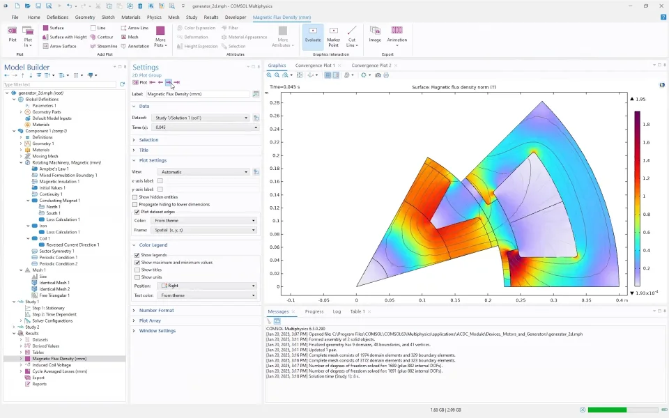
Sector modeling is a technique in COMSOL Multiphysics that reduces computation time by simulating only a repeating fraction of an electric motor's geometry rather than the full model. Because coils and magnets typically repeat in a circular, alternating pattern, only one representative sector needs to be modeled, with the remaining geometry treated as periodic. In a simple generator example featuring eight poles and eight slots, the geometry can be divided into one-eighth sectors. The number of sectors is determined by the greatest common divisor between the number of poles and the number of slots.
Building a sector begins by drawing a circle with a sector angle of 360 degrees divided by the number of sectors, then using Boolean intersections and partitions to isolate the stator and rotor portions. A form assembly step creates an identity boundary pair at the rotor-stator interface, which should always be verified along with material assignments after modifying geometry. The rotating domain in the moving mesh setup remains unchanged, with only the rotor rotating. In the Rotating Machinery, Magnetic interface, a Sector Symmetry feature is added under Pairs and assigned to the identity boundary pair, and the number of sectors is entered as a parameter. The symmetry type is either continuity or anti-periodicity: as a rule of thumb, an odd number of poles in the sector requires anti-periodicity, while an even number allows continuity. Alternating coil and pole directions in the example make anti-periodicity the correct choice.
The outer boundaries of the sector must be defined as periodic using a Periodic Condition on the interface, applied separately for rotor and stator parts with automatically assigned source and destination boundaries. Circular magnet patterns are removed since only one magnet remains in the sector. For meshing, generating a physics-controlled mesh first and then converting to a user-controlled mesh produces an identical mesh feature that matches source and destination boundaries at the periodic conditions. This identical mesh significantly improves convergence when values are mirrored or anti-periodically transferred between sides. Cutting permanent magnets in half is numerically challenging because a magnet interface acts as a flux singularity; while acceptable in 2D, it is advisable in 3D to rotate the cutting circle slightly so the magnet is left intact rather than divided.
When interpreting results, quantities calculated over a single sector must be scaled appropriately. Induced voltages and cycle-averaged losses, such as those integrated over an iron domain using rmm.Qh, represent only one sector and must be multiplied by the number of sectors to obtain full-model values. In contrast, the Arkkio torque calculation in the air gap automatically incorporates the number of sectors from the continuity or sector symmetry feature, so the computed torque (rmm.T) already reflects the full model and requires no additional scaling. This content is part three of the online course Modeling Electric Motors with COMSOL Multiphysics, covering the fundamentals of sector modeling including periodicity selection, magnet cutting considerations, and correct result scaling.
Further Learning
- Using Symmetry to Reduce Model Size: article covering the benefits of reducing your model size with symmetry
- Exploiting Symmetry to Simplify Magnetic Field Modeling: blog post demonstrating how symmetry can be used to model electromagnetic fields
- Modeling of an Electric Generator in 3D: tutorial model of a 3D motor built with sectors
Submit feedback about this page or contact support here.


