

Fusion energy is 30 years away — and always will be.
The joke certainly rings true for inertial fusion energy (IFE), which must overcome a number of obstacles before it can become a reality. For example, the current methods for creating IFE targets cannot meet the predicted demand and cost requirements. To solve this problem, researchers designed a new microfluidics method that could address these production bottleneck issues while complying with the strict geometrical requirements of IFE target design.
Addressing the Challenges of IFE Target Production
To produce inertial fusion energy (IFE), inertial confinement fusion (ICF) uses multiple powerful lasers to heat target shells that are small (around 2 mm in diameter), concentric, and highly spherical. The shells contain nuclear fuel in the form of frozen hydrogen isotopes that, when compressed and heated to a certain temperature (~100,000,000 degrees Celsius), undergo nuclear fusion.
Typical fusion reactors will consume around 1 million of these target capsules per day. Thus, there are two requirements for this type of fusion to be commercially feasible:
- The cost of the target shells must be around $0.20 per unit
- The production process must be fast enough to keep up with demand
At the same time, the capsules need to maintain certain specifications. Professor Barrow, part of a research team from the School of Engineering, Cardiff University, says that IFE capsules require “not only >99.99% sphericity and concentricity and less than 50-nm surface roughness, but they may also need inner reflective coatings, light scattering properties, and to be extremely rugged — since they would be fired at 1000 m/s from a pneumatic gun and contain frozen nuclear fuel at a temperature of ~18 K!”
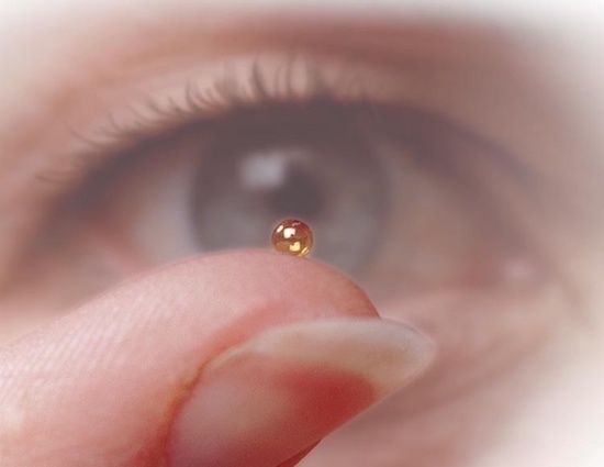
A microcapsule that can be used in ICF. Image in the public domain, via Wikimedia Commons.
Achieving these IFE production goals isn’t possible with the current methods of target fabrication, which produce targets in a bespoke manner and at a high price tag — a few thousand dollars each. This issue poses a critical challenge for IFE generation.
The research team from Cardiff University aims to help tackle this problem. Their possible solution? A continuous flow reactor method that uses multiphase droplet microfluidics to generate monodisperse double-emulsion droplets. These droplets can then be used as templates to fabricate the shells needed for IFE targets. Let’s look at the researchers’ process in the next section.
Analyzing the 3 Steps of a Novel Method for IFE Target Production
There are three steps in the new process for IFE target shell production:
- Forming double-emulsion droplets
- Centralizing the double-emulsion droplets
- Ultrafast shell-phase polymerization
The researchers studied and optimized each of these steps with experimental tests and simulation.
Step 1: Forming Double-Emulsion Droplets
Using a new bat-wing fluidic junction, the researchers were able to form monodispersed double-emulsion droplets. They examined the flow patterns of the droplet-formation process with two-phase laminar flow simulations.
The results reveal a satellite droplet removal mechanism. The droplets momentarily remain in a stationary position within a “still zone” of the bat-wing junction, enabling them to merge with subsequent droplets of the dispersed phase. This mechanism enhances the uniformity of the double-emulsion droplets.
At the end of this step, the double-emulsion stream rises vertically through an optofluidic reactor, which incorporates multiple UV LEDs for precision photocuring of the target shells.
Step 2: Centralizing the Double-Emulsion Droplets
The second stage of the process involves centralizing the droplets in a dynamic fluid. Here, the researchers used the COMSOL Multiphysics® software to evaluate the droplet position and shape while in the flowing carrier fluid. Their goal was to optimize the concentricity and sphericity of the double-emulsion droplets — fulfilling the geometry needs of IFE targets before the target shell polymerization stage, which generates a fixed geometry.
The team achieved droplet centralization in the flow, which rises vertically, by tuning the flow parameters in the scenario of a gravity and solvent density mismatch. The conditions of the flow were optimized with the Microfluidics Module, which the researchers used to determine the key input parameters that need to be adjusted to generate concentric and spherical droplets.
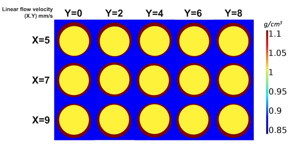
Using simulation to perform a shape optimization study of double-emulsion droplets under different flow conditions. Image courtesy Jin Li.
The researchers used a droplet detection device (consisting of a red laser emitter, phototransistor, and microprocessor) to evaluate the double-emulsion droplet shapes as they formed. Using this tool shows that when rising vertically through the horizontal detection beam, a nonconcentric droplet causes a “V”-shaped signal due to the droplet’s morphology. On the other hand, a concentric droplet creates a “W” signal shape because of the equal lensing effects at its polar regions.
The research team concluded that since the shape of the double-emulsion droplets causes different phototransistor detection signals, these signals could be used to determine the shape of the droplets. For example, a “W”-shaped phototransistor signal indicates that the droplet has sufficient concentricity for the photocuring process. Simulations created using the Ray Optics Module, an add-on product to the COMSOL Multiphysics® software, verify these findings.
Step 3: Ultrafast Shell-Phase Polymerization
In the third step, the droplets generated in the previous stages are cured one-by-one to be used as templates for IFE shells. This curing is achieved via an optofluidic reactor that uses UV LEDs with a coded processor for automated actuation. With simulation, the geometry of the reactor is optimized to ensure that it generates a uniform UV irradiation at its center with the presence of fluids. The uniform irradiation should enable the reactor to perform homogeneous photopolymerization in the shell layer of the droplets, helping to form spherical and concentric shells. The quality of these shells depends on the timing, droplet movement, flow conditions, and uniformity of the light curing.
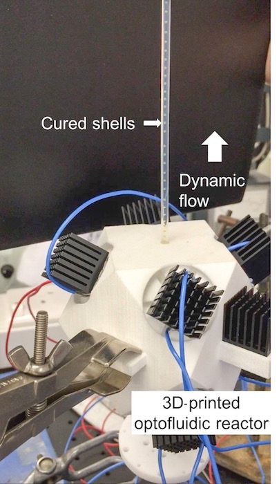
The optofluidic reactor used to cure polymeric shells. The finned heat sinks of each LED are also seen. Image courtesy Jin Li.
The general photocuring process is as follows:
- After a droplet is initially detected, there is a delay (d) to enable the droplet to move to the middle of the UV irradiation field
- The LEDs temporarily actuate for the duration of exposure, T (ms), and cure the droplet
With the current design, the researchers fixed T at 70 ms. Meanwhile, they found that changing d at intervals as low as 1 ms results in varied globular forms for the capsule shells. For example, with a certain input flow rate, when d is 163 ms, the form of the solidified shell is approximately concentric and spherical. However, when d is between 160 ms and 162 ms as well as 164 ms and 167 ms, the shells are pearl shaped. Other values of d didn’t even generate continuous shells due to the refinement of UV light by the internal structure of the reactor. The shape variations might be the result of uneven energy absorption of the UV light, which can cause uneven photopolymerization inside the shell.
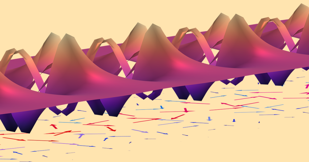
With simulation, the researchers were also able to evaluate how droplet movement affects the final shell quality. The total amount of UV light on the shell layer varies depending on the precise location of the droplet. For instance, within the shell phase, the energy distribution of the light is relatively uniform when droplets are located on the reactor’s optical focus point. The amount of light changes when the droplet is in motion. When droplets are further from the reactor’s optical focal point, the light energy distribution is more discretized — resulting in more high-energy spots in the shell layer.
The difference in light energy could alter the photopolymerization rate and result in variations of shrinkage and stress within the curing polymer layer, possibly leading to cured shells that are less spherical and concentric. To address this issue, the team needed to create a uniform curing process that evenly delivers UV light. When using a process that continuously cures individual droplets, evenly delivering UV light can be achieved by using short UV exposure times from the light sources.
Advancing Fusion Energy with a New Method for IFE Target Shell Production
Dr. Jin Li, another researcher on the team, says that the new approach “exhibits a promising way to scale up such IFE target fabrication.” The novel method can potentially increase the IFE target production rate to meet future demands. He also notes that the resulting ready-to-use polymeric shells are close to the target specifications, as the “yield rate of [the] shells is nearly 100%, produced at up to 15 Hz, and with both an average 99.41% shell concentricity and 99.41% shell sphericity, since the monodisperse droplets were processed individually in the flow by the same manner.”
Regarding the cost of production, Barrow notes that the new method could enable them to produce IFE shells at close to the target price ($0.20 per unit). The process is also automated and highly replicable. Further, by varying the flow conditions, different sizes of double-emulsion droplets can be produced. This means that researchers can use this technique to fabricate shells with different dimensions, fulfilling the requirements of various ICF reactors.
Barrow also mentions that in the field of energy production, “fusion energy could save the planet, but one downside is that it remains extremely sophisticated and centralized.” With simulation research, these challenges can be addressed, paving the way for the realization of fusion energy.
Additional Resources
- Read about the researchers’ original work: “Continuous and scalable polymer capsule processing for inertial fusion energy target shell fabrication using droplet microfluidics“
- Learn more about the bat-wing fluidic junction in a previous blog post and the related research paper


Comments (3)
Abdulfatai Faro
September 30, 2017This is really interesting and I hope to see it scale up in years to come. Kudos guys
Caty Fairclough
October 3, 2017Hi Abdulfatai,
Thanks for your comment! I’m glad that you enjoyed the blog post.
brahim taoufik
November 29, 2018This is really interesting