Do you often find your office too hot, even as your coworkers are shivering? Or perhaps it’s the other way around, and you’re the cold one. As with the age-old question of whether a glass is half full or half empty, the perception of ambient temperature can vary widely from person to person. To ensure maximum comfort among a building’s occupants, heating, ventilation, and air conditioning (HVAC) system engineers can precisely assess indoor climate conditions with multiphysics simulation.
Cool Breeze or Icy Draft? It Depends…
Is that air moving past us a cool breeze, or an icy draft? It depends on who you ask…
A model developed by Mika Maaspuro, who specializes in simulations related to the built environment, reveals the spatial variations in temperature and airflow that affect people’s comfort, even in a relatively small room. These results suggest adjustments to HVAC system design that could save energy and better accommodate individual climate needs.
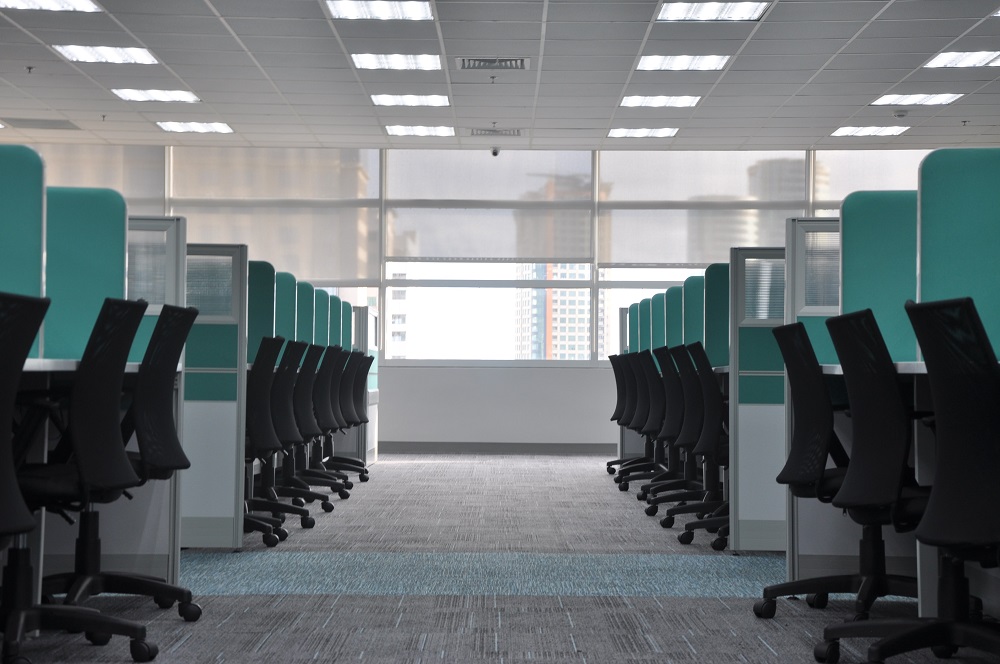
The ideal office temperature varies from person to person. Photo by kate.sade on Unsplash.
What are those needs, and how does a preferred indoor climate differ from person to person? The conditions that we perceive as ideal vary more than you might expect. “Research shows there is a range of up to 6°C [10.8°F] in what most people perceive as the most comfortable temperature,” says Maaspuro. “Thermal perception varies from person to person, from men to women, and is affected by time of day, as well as the movement of air across our bodies,” he explains.
“For example, a person who feels warm at 22–23°C [71.6–73.4°F] wouldn’t really notice an air velocity of up to 0.4 m/s,” Maaspuro says. “A person who already feels cold at that temperature, however, would find that same breeze to be an unpleasant draft.”
Smart Buildings Can Provide More Granular HVAC System Design
Our acute sensitivity to air temperature and movement makes HVAC system design a perpetual challenge. Typically, these systems are based on a single temperature sensor that switches a heating/cooling unit on or off. “It’s very simple, but not very flexible or efficient,” Maaspuro says. His research focuses on the development of smart building systems that better regulate the indoor environment.
While these systems are generally intended to improve building security, save energy, and otherwise reduce costs, they also provide the potential for fine-tuned management of the indoor climate. “We want to find technical solutions that enable each person to feel comfortable in the climate they share with others,” says Maaspuro.
Simulating a Shared Office Space in COMSOL Multiphysics®
Since multiple factors shape perceived climate conditions, multiphysics simulation can help pinpoint the slight variations that have a big impact on human comfort. For this project, Maaspuro used the COMSOL Multiphysics® software to model a small room that was quite familiar to him, as it’s based on the office he shares with others at Aalto University in Finland.
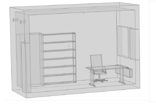
A cutaway view of Mika Maaspuro’s 4 m x 5 m x 3.5 m (height) office model. The image shows half of the model geometry, and only half is considered in the simulation due to symmetry. Air inlet and outlet vents are mounted in the wall above the door at left. The heating unit is mounted in the wall under the window at right. Along with the desk and chair shown here, the actual room includes space for additional occupants closer to the door. The room is enclosed by walls, the floor, and the ceiling, with thermal characteristics specified by typical heat transfer coefficients and heat capacities.
The simulation couples heat transfer in solids and fluids and laminar flow, and was constructed using the Events interface in COMSOL Multiphysics. Even in this moderately small space, temperature and airflow conditions can vary widely, so the model includes thermostats in multiple locations, including one near the door and another near the radiator under the window. The time-dependent 24-hour simulation tracked the temperature at each thermostat location, and also the resulting on/off operating cycle of the heating unit. This enabled Maaspuro to compare how thermostat placement affects localized temperatures, as well as its impact on heating unit runtime.
Too Hot? Too Cold? Or Both?
The simulation reveals overall patterns of temperature change and airflow, which help explain the resulting localized conditions.
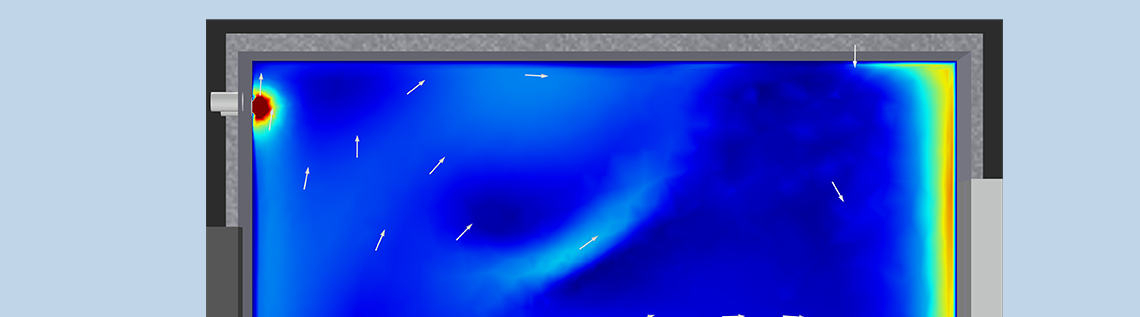
Simulated temperature (°C) in the room over a 24-hour period. Sample is taken from a slice on the zy-plane at x = room width/4. The room thermostat is set to 23°C. Ventilation air is 18°C, 6 l/s per person (total 12l/s due to symmetry).
Airflow speed at the same location and under the same conditions as described above.
As shown above, the highest temperature is found on the floor in front of the radiator, while airflow speed is highest along the ceiling. The air movement caused by the high-mounted vent pushes cooler air along the ceiling and down the wall where the window and radiator are located. This air then “picks up” the radiator’s heat and flows along the floor, gradually releasing heat into the higher parts of the room.
This cyclical process is reasonably effective at distributing heat, but it does create spatial irregularity that will affect people’s comfort. The corners of the room are notably colder than the space near the radiator, as is the space closest to the door. People sitting near the radiator may be sweating, even as someone near the door has chilly feet. The localized simulation results quantify this effect and suggest next steps.


A comparison of average room temperature (left) and on/off heater cycling pattern over a 24-hour period (right), as controlled by a single thermostat located near the door.
In a dispute over whether a room is too cold or too hot, both people may be correct. In the simulation where the thermostat is mounted near the door, the room’s average temperature fluctuates rather widely. When the thermostat is placed by the radiator, the temperature swings are reduced, but the resulting average temperature will be colder. Also note that the on/off cycles of the heating system are shorter when the thermostat is close to the radiator. This rapid cycling can be annoying — especially if the occupants are trying to concentrate on their work as the system repeatedly turns on and off!

Comparison of average room temperature and on/off heater cycling pattern over a 24-hour period, with exterior airflow volume increased to 12 l/s per person (total 24 l/s). The two plots at left are for the thermostat placed near the door, and the plots at right show results for placement by the radiator.
The results above show how increasing the rate of airflow affects overall temperature and heater cycles for both thermostat locations. Moving larger volumes of air brings the average temperatures somewhat closer, while creating steeper peaks and troughs in the overall trends. Increased circulation also leads to an even more rapid and irregular on/off cycle for the heating unit, no matter where the thermostat is located.
More Thermostats May Mean a Happier Workplace
What conclusions can be drawn from these analyses? Perhaps the clearest finding is that, as Maaspuro says: “Thermostats are commonly placed near radiators, but this is probably the worst location.” If the sensor is close to the heater, then the average room temperature is likely to be lower. Also, simply moving the thermostat doesn’t entirely address the problem, and neither does increasing airflow.
The solution? “The best approach is not either/or — it’s both,” says Maaspuro. “The most effective control system would sample temperature in both locations, and then calculate an average temperature. This would make the overall climate more comfortable by reducing variation throughout the room.”
Next Step
Learn more about the research discussed here by reading Maaspuro’s presentation from the COMSOL Conference 2020:


Comments (3)
Ivar KJELBERG
June 25, 2021Nice and interesting presentation.
Now, my experience is that the “comfort” feeling of us humans also depends a lot on the radiation exchange, I believe many of us are also very sensitive to the radiation exchange of the skin to the external T temperature (of a sweater, or the walls, or deep sky for outside) than even to some draught of “cold” or hot “air”.
So one could add some surface + thermal isolation treatments on the wall, floor, ceiling regions around the people in the room, such that these surfaces exchange efficiently with the air and participate to give a positive radiation environment, and radiation exchange is easily added to a COMSOL Multiphysics® HT model.
Alan Petrillo
June 28, 2021 COMSOL EmployeeThank you, Ivar, both for reading and for the thoughtful suggestion!
Ivar KJELBERG
July 8, 2021Hello again,
Well there is more here, one thing is the lost heat during air exchange, particularly for us with winters, or those with really hot humid outside ambient air. For that it was proposed once on a project, quite some years ago, to have several inlet – outlets, communicating and working in tandem to exchange the air, and in the same time embed a heat exchanger (i.e. a porous PET plastic block) such to keep some of the heat or cold expelled. And then to regularly reverse the operation such to reuse the heat / shill of the heat exchanger block.
And then we have all the issues with the dew point, freezing etc. All this is now nicely available in COMSOL, making it really efficient for such analysis.
Still a nice model is not a working product, quite some work to get it on the market 🙂
Have fun COMSOLing
Sincerely
Ivar