
When you are working with foreign CAD data, such as files in STEP or IGES file formats, you may think that you need to re-import a new CAD file and start your modeling over from scratch if you want to study a change in size or shape. But, in fact, you can modify the geometry that you’ve imported with some clever usage of the Deformed Geometry interface in COMSOL Multiphysics. Here, we will look at how this can be done.
Importing, Meshing, and Analyzing a CAD File
A vendor-neutral CAD file, such as a STEP or an IGES file, contains the boundary representation of the solids you wish to model. You can import such files into COMSOL with the CAD Import Module. You can also import ECAD layout files, such as GDS, with the ECAD Import Module. Once the files are imported, you can use them for analysis. For example, below you can see a model of a wrench and bolt that has been imported, meshed, and solved for an applied load.
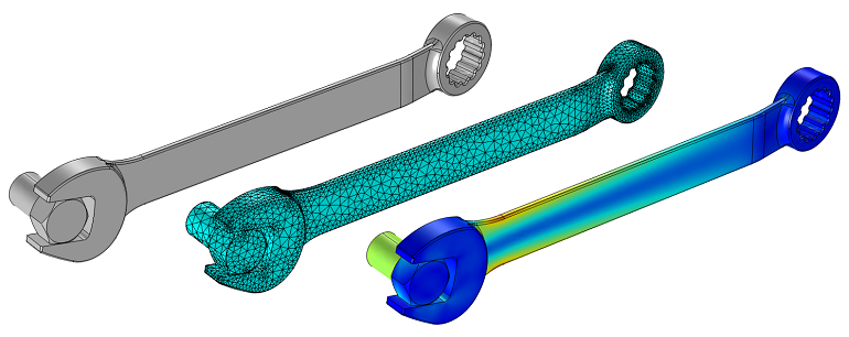
The CAD file itself only contains a description of the geometry and doesn’t contain any information about the features and history of the part, so we cannot modify variables such as length, for example. (Now, if we were using one of the LiveLink™ products that connect COMSOL to CAD software, we could simply modify the file in the original CAD package. Although, we sometimes do not have this option.) Luckily, even in this case, there is a solution!
Modifying the Imported CAD
Let’s go through an example of how we can modify this imported CAD file of a wrench with the objective of studying different wrench lengths. The first thing that we will do here is to create a cylinder with the length of 1 cm, place it at the origin, and use it to Partition the wrench into three domains. We then mesh the part using a Swept mesh in the middle section to accommodate the geometric changes that we will implement. We could also have used a tetrahedral mesh but the swept mesh gives us better control over the elements.
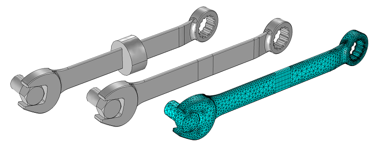
Next, we introduce a Deformed Geometry interface. This allows us to specify how the geometry will change. Also, let’s introduce a Global Parameter called dLength to represent the difference in length. With this, we specify the deformation of the domain at the far end of the wrench to be (dx,dy,dz) = (dLength,0,0) while leaving the deformation of the neat end as a fixed geometry. In the intermediate domain, we prescribe a deformation of (dx,dy,dz) = (dLength*(Xg/1[cm]),0,0).
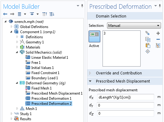
This expression makes use of the Geometry Frame Coordinates, (Xg,Yg,Zg), which is a coordinate system that refers to the original CAD geometry. The partitioned domain starts at Xg = 0 and ends at Xg = 1 cm. This expression applies a linear stretching to the middle domain. We can now run a Parametric Sweep over the dLength and take a look at the results.
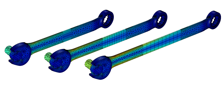
Observe that the mesh in the central region has been stretched. To accommodate for this, we use a swept mesh in this region.
We have now computed the stresses in the wrench for three different lengths, just by using the original CAD file and the Deformed Geometry interface.
If you would like to access the files used here, please go to the Modifying Imported CAD Geometry with the Deformed Geometry Interface model in the Model Gallery. If you are interested in learning more about using COMSOL Multiphysics for your analysis needs, please contact us.



Comments (3)
Ivar Kjelberg
January 9, 2014Hi Walter,
thanks for a nice and illustrative example
Indeed with the Geometry Frame you can do subtle cases
If you want another subject I would appreciate to see in the “how to” blog:
How to link different Parametric Sweep such that the initial conditions of a second separate study is correctly indexed into the correspondent parametric index of a first parametric study
The solver node has quite some setting options for the initial conditions, to choose between current, stored, parametric …
Linked to this comes the “continuation sweep” versus “external sweep” and the new ways in 4.4 you propose to select options how COMSOL links the “continuation”
Having real fun COMSOLing
Ivar
Dag Herman Andersen
November 1, 2016Vey good example. Thanks for the application files
Constantinos Tsangarides
December 12, 2019Hi Walter,
I tried this example on the wrench file and it works. However, if I create the partition at a different location (not at origin) the wrench does look like it has its three parts disconnected from each other. How can I fix this issue?
Kind regards,
Constantinos