RF Module
New App: Slot-Coupled Microstrip Patch Antenna Array Synthesizer
Microstrip patch antenna arrays are used in a number of industries as transceivers of radar and RF signals. This is a prime candidate for the 5G mobile network system.
The Slot-Coupled Microstrip Patch Antenna Array Synthesizer simulates a single slot-coupled microstrip patch antenna, fabricated on a multilayered low-temperature cofired ceramic (LTCC) substrate. When using this app, you will be able to simulate the far-field radiation pattern of the antenna array and its directivity. The far-field radiation pattern is approximated by multiplying the array factor and the single antenna radiation pattern to perform an efficient far-field analysis without simulating a complicated full-array model.
You can also evaluate phased antenna array prototypes for 5G mobile networks with the default input frequency, 30 GHz. You can do this by varying antenna properties such as the geometric dimension and substrate material.
An added feature of this app is the option to view it on either a narrow or a wide screen.
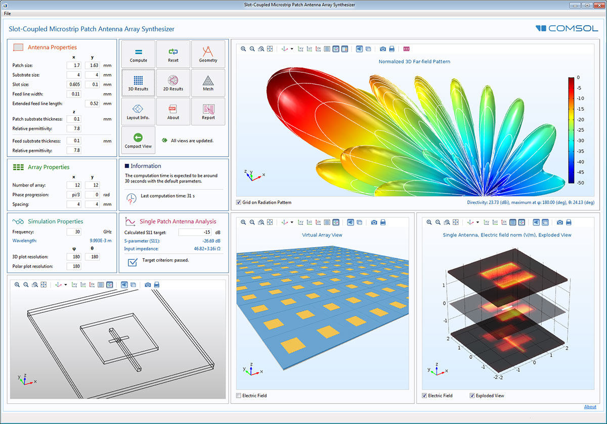 The user interface of the Slot-Coupled Microstrip Patch Antenna Array Synthesizer app, with a 12x12 virtual array, electric field distribution, and 3D far-field radiation pattern view.
New App: Frequency Selective Surface Simulator
Frequency selective surfaces (FSS) are periodic structures that generate a bandpass or a bandstop frequency response. They are used to filter or block RF; microwave; or, in fact, any electromagnetic wave frequency. For example, you see these selective surfaces on the doors of microwave ovens, which allow you to view the food being heated without being heated yourself in the process.
The Frequency Selective Surface Simulator app simulates a user-specified periodic structure chosen from the built-in unit cell types. It provides five unit cell types popularly used in FSS simulations along with two predefined polarizations in one fixed direction of propagation that has normal incidence on the FSS. The analysis includes the reflection and transmission spectra, the electric field norm on the top surface of the unit cell, and the dB-scaled electric field norm shown on a vertical cut plane in the unit cell domain.
You can change the polarization, center frequency, bandwidth, number of frequencies, substrate thickness and its material properties, and unit cell type (circle, ring, split ring, etc.) as well as their geometry parameters, including periodicity (cell size).
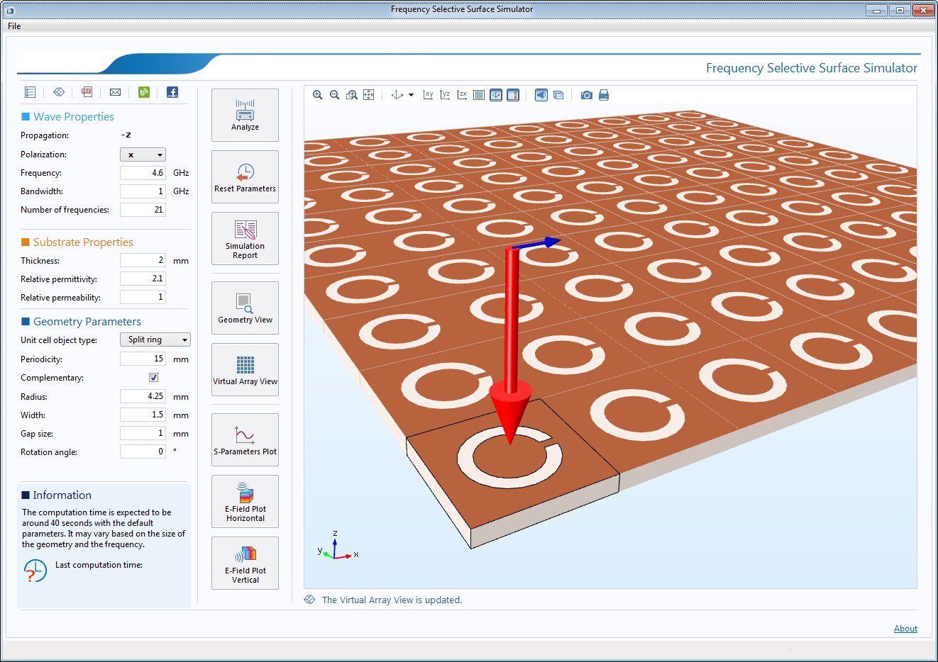 The user interface of the Frequency Selective Surface Simulator app, with a 10x10 virtual array view using a split-ring cell type.
Smith Plots: A Conventional Way to Present Matching Properties
A new Smith plot group allows you to plot impedance, admittance, and reflection data in a Smith grid. Smith plots are useful for relating complex-valued S-parameters (reflection coefficients) to input impedance, admittance of antennas, transmission lines, or other network components. For studies where an S-parameter plot is generated by default, a Smith plot is automatically generated.
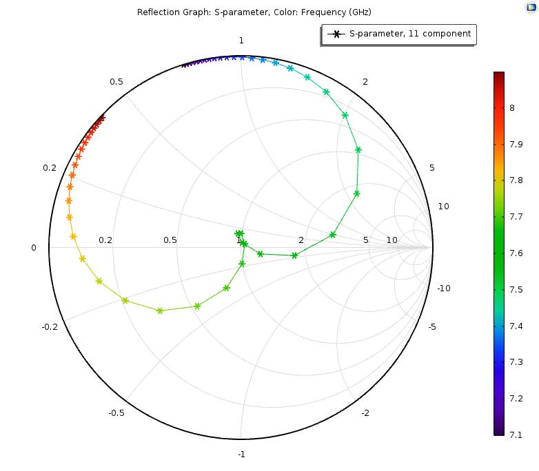 Smith plot of the CPW bandpass filter where the color scale indicates the simulation frequency, showing that the filter is matched to 50 Ohm around 7.65 GHz.
Enhanced Physics-Controlled Mesh for Handling Lossy Media
The physics-controlled mesh takes lossy electric and magnetic media and automatically scales the size by skin depth on the lossy domain boundaries. When Resolve wave in lossy media is selected, the outer boundaries of lossy media domains are meshed in free space with a maximum mesh element size, given by the minimum value of half of a skin depth and 1/5 of the vacuum wavelength.
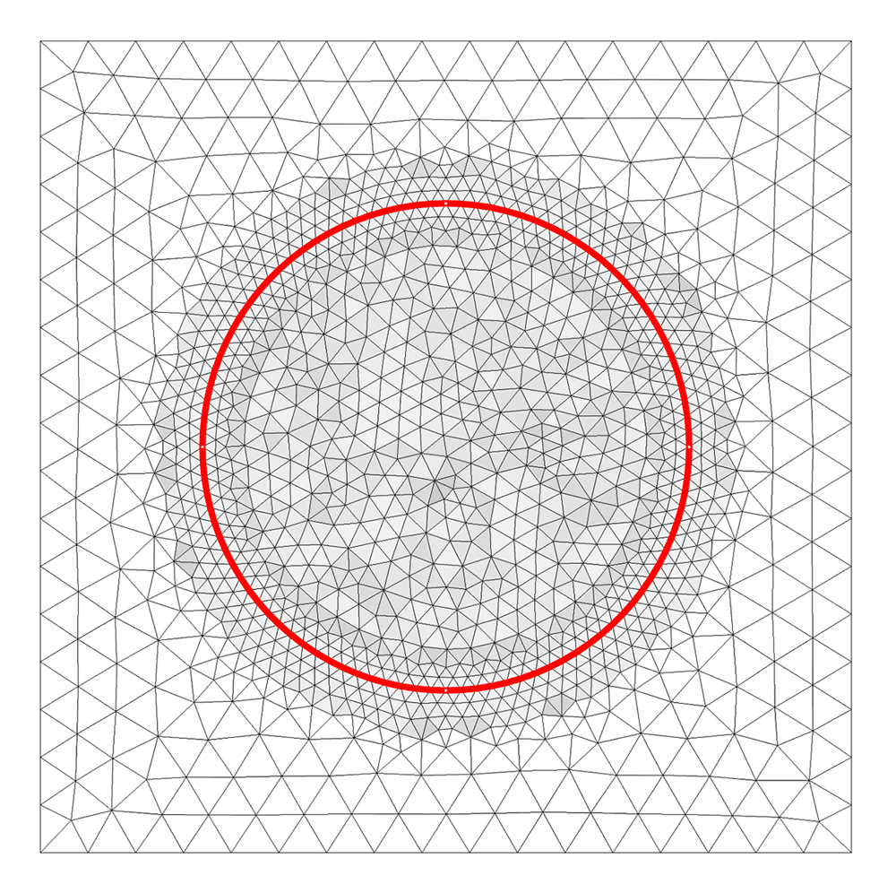 Finer mesh along the outer boundary of a circular lossy media in the air is characterized by the skin depth with these material properties: loss tangent and dissipation factor (ε' = 1.2 and tanδ = 3.5) at 1 GHz.
Multielement Uniform Lumped Port
A new lumped port type is included in COMSOL Multiphysics version 5.2, the Multielement uniform port. This lumped port type can be used for multiexcitation or multitermination of, for example, a coplanar waveguide port or a differential port. The direction of the field in each subelement of the port is defined by the Uniform element subnodes, where the direction between uniform element terminals, ah, defines the electric potential polarity.
New Model: Coplanar Waveguide (CPW) Bandpass Filter
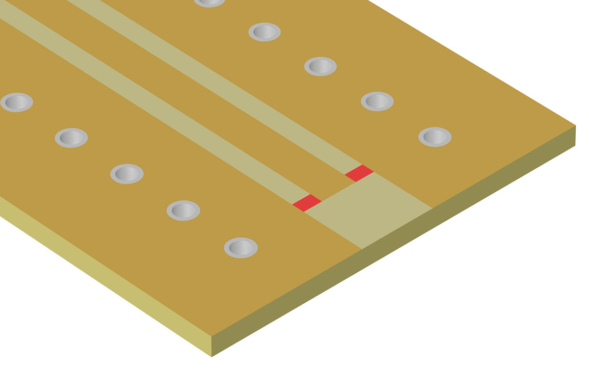
Coplanar waveguide (CPW) bandpass filters can be designed using interdigital capacitors (IDCs) and short-circuited stub inductors (SSIs). This is a very efficient manufacturing method for producing bandpass filters, which can readily be implemented on a GaAs wafer.
The Coplanar Waveguide Bandpass Filter tutorial model presents a design that is compact in relation to its resonant frequency and provides a relatively high Q factor as compared to capacitively coupled microstrip line model designs. It uses the Multielement uniform lumped port feature of the COMSOL Multiphysics software in order to excite and/or terminate each element of the respective ports equally.
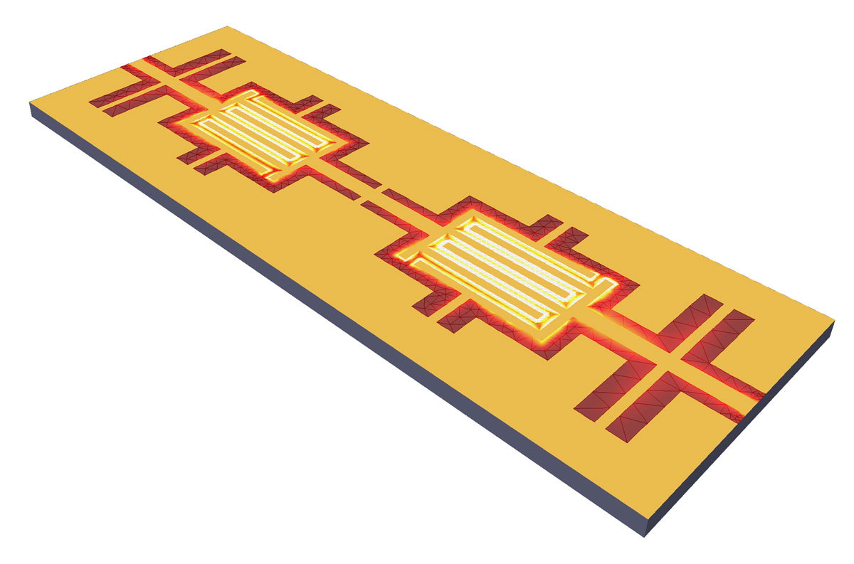 A coplanar waveguide bandpass filter on a 200 mm GaAs wafer composed of an interdigital capacitor and short-circuited stub inductors.
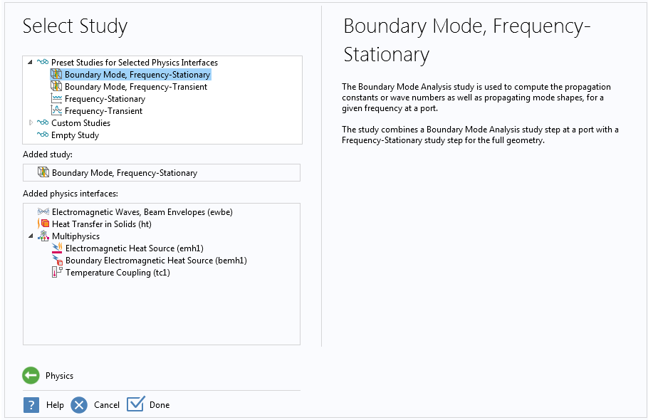
"Boundary Mode, Frequency-Stationary" and "Boundary Mode, Frequency-Transient" Study Sequences
There are new study sequences in the Model Wizard for the Laser Heating and Microwave Heating multiphysics interfaces in the Wave Optics and RF Modules, respectively. The Boundary Mode, Frequency-Stationary study sequence adds a Boundary Mode Analysis study step and a Frequency-Stationary study step. The Boundary Mode, Frequency-Transient study sequence adds a Boundary Mode Analysis study step and a* Frequency-Transient* study step. The Boundary Mode Analysis study step is used for solving the mode field for numeric ports in the electromagnetic interfaces. The Frequency-Stationary and Frequency-Transient study steps couple stationary and transient analyses for the Heat Transfer in Solids interface, with a frequency domain analysis for the Wave Optics and RF interfaces.
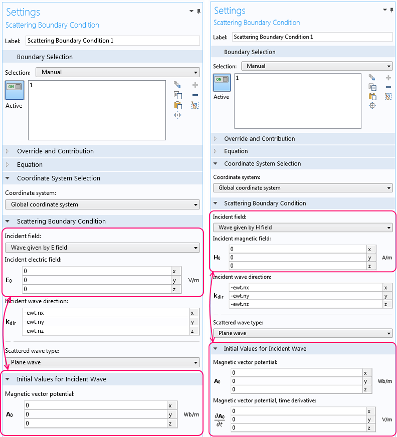
Initial Value Settings for the Transient Scattering Boundary Condition
In the settings for the Scattering boundary condition for time-dependent simulations, there is a new section called Initial Values for Incident Wave for setting the initial values of the magnetic vector potential for the incident wave. Note that the section is initially collapsed by default. When the incident wave is defined by an electric field, the user can specify the initial value for the magnetic vector potential for the incident wave. When the incident wave is defined by a magnetic field, the user can specify the initial value for the time derivative of the magnetic potential, in addition to the initial value for the magnetic vector potential. The new settings enable the user to define the exact wave form for the magnetic vector potential being solved for.