

When you speak up in a virtual meeting, recite voice commands into smart devices, or talk over the phone, there’s a good chance it’s MEMS technology that picks up your voice. This is due to the frequent use of this solid-state semiconductor technology in creating small speakers that produce high-quality sound. In this blog post, we explore the benefits that MEMS bring to microphones, the challenges that come with producing MEMS microphones, and how modeling and simulation can help make the design process of these microphones more efficient. We also discuss the latest advancements in modern microspeakers driven by MEMS technology.
MEMS Now
Using MEMS technology in microphones adds a high signal-to-noise ratio (SNR), the ratio between the desired audio signal and the level of background noise. And due to the small size of MEMS, it is possible to add multiple microphones to a device, such as laptops or phones. The ability of MEMS to provide high SNR combined with the benefits that come with their compact size enable MEMS devices to have filtering and active noise cancellation (ANC). This is what allows MEMS microphones to pick up clear voice signals and filter out noisy ambience from the outside world. In addition, the silicon structure of MEMS microphones makes them easily integrated with digital products, resistant to technical vibration, and inexpensively mass produced.
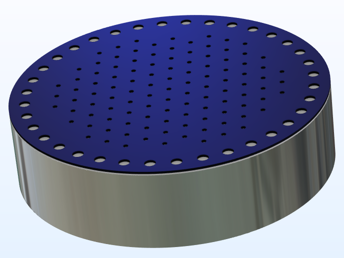
Figure 1. A MEMS microphone.
Due to all of the benefits that they provide, MEMS technology is increasingly being used in microphones in consumer products, such as smart home devices, cellphones, tablets, desktop and laptop computers, and hearing aids. In recent years, the need for MEMS microphones has become even more important as work-from-home scenarios have risen.
Modeling a MEMS Microphone
Looking inside technology this small is made easier with simulation software, where engineers can accurately model the device and zoom in on the different areas of interest. At the small scale of the MEMS microphones, typically the submillimeter scale, the effects of the thermal and viscous boundary layers are important. The boundary layers are responsible for both frictional and thermal losses in the system, which will dampen the acoustic response. It is important to include the viscous and thermal effects to get the correct acoustic response of a MEMS microphone.
As manufacturing techniques continue to develop, it is possible to manufacture smaller and smaller devices. However, the smaller sizes lead to high Knudsen numbers, making noncontinuum effects important. With simulation, engineers can test multiple variables. For example, with our model of a MEMS microphone, you can use a boundary condition to include the effects of high Knudsen numbers in a MEMS microphone.
The microphone consists of a microperforated plate (MPP), a vibrating diaphragm, and a closed backing volume. A slip condition has been applied to the diaphragm’s surface so that the tangential velocity at the wall depends on the fluid’s stress at the boundary. This creates a discontinuity between the velocity of the solid and the fluid.
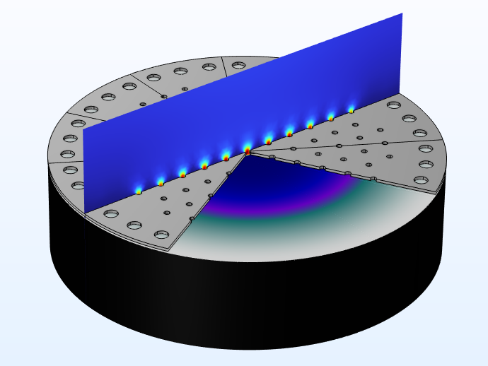
Figure 2. MEMS microphone consisting of an MPP and a vibrating membrane.
Next, we’ll briefly go over some of the results from the model. Feel free to jump ahead to the step-by-step instructions for building this model by downloading it at the bottom of this blog post.
Exploring the Results
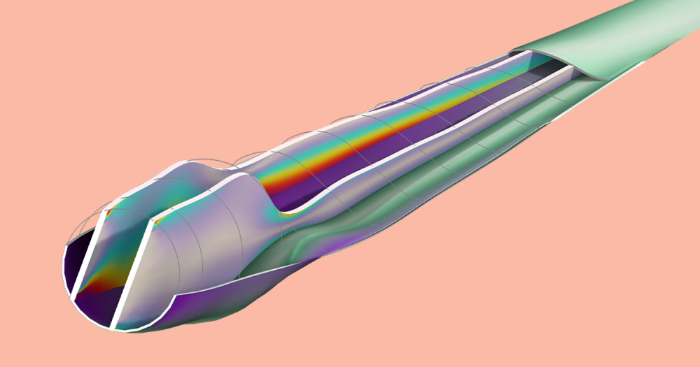
At the beginning of the study, an electric field prestresses the diaphragm to give it a stationary deformation, much like tightening a guitar string. Pressure is then applied to the surface above the MPP, making the diaphragm vibrate and cause an electric signal in the space between the two parts, as shown in Figure 3.
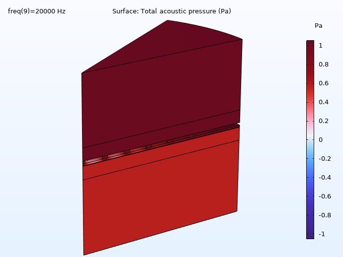
Figure 3. Acoustic pressure in all domains at 20 kHz.
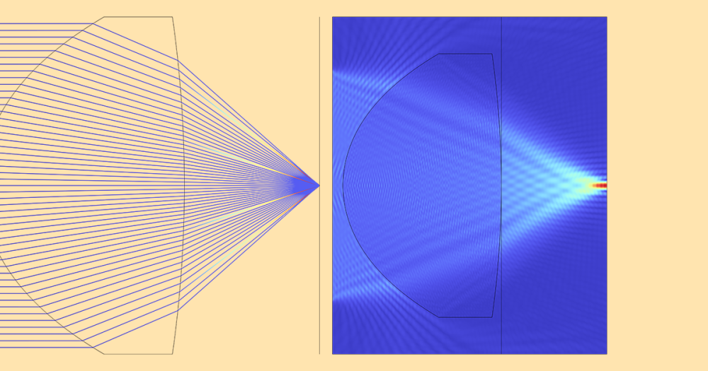
Investigating the acoustic velocity, as shown in Figure 4, reveals the areas of viscous damping are via the holes in the MPP and the squeezing flow between the MPP and diaphragm.
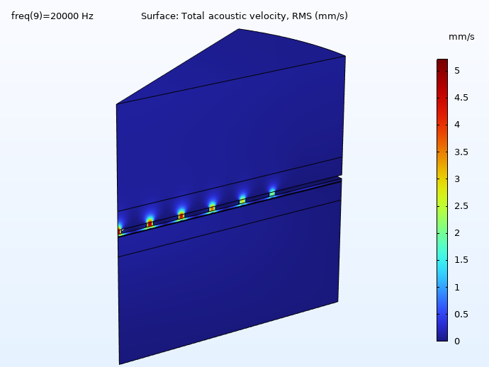
Figure 4. Acoustic velocity.
Lastly, the frequency response of the MEMS microphone from 200 Hz to 20 kHz is analyzed. Lower frequencies show a roll-off in which the response ceases to be flat due to the coupled electric circuit, while the response drops off at the higher frequencies. Mechanical resonances are located at higher frequencies due to the small length scale of the model, and therefore the spectrum is near to flat in the audio range.
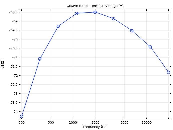
Figure 5. Frequency response.
MEMS microphones are common in everyday devices and are consistently being improved with the help of modeling and simulation. Next, we’ll explore a new avenue of use for MEMS that could also benefit from the use of simulation in the design process.
A New Trajectory
The benefits of MEMS microphones also apply to MEMS speakers, but up until very recently, the speaker technology was not commercially available. Speaker technology often relies on the same mechanical system it did at its invention, consisting of a magnet, a coil, and a diaphragm. This system has been improved over the decades, but most speakers encounter similar design challenges, especially concerning headphones. The magnet and coil system can be susceptible to discrepancies in phase alignment, which can lead to differing sound in each ear. The diaphragm itself often isn’t stiff enough to keep a piston-like motion for high frequencies: the diaphragm can warp when responding to the magnet push, which runs the risk of muddying some sounds.
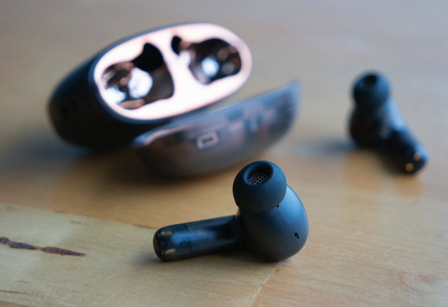
Figure 6. Headphones featuring MEMS drivers.
MEMS technology provides solutions to these problems. Because of its solid-state semiconductor construction, a MEMS speaker removes the magnet, making the speaker lighter and smaller, and production is more uniform, eliminating phase misalignment. The silicon diaphragm is stiffer and stays linear when pumping air, so the sound stays clear and unmuddied. In addition, MEMS speakers have faster actuation than a magnet and coil speaker, which means they are faster at initiating and ending a sound and therefore provide a clearer separation between different sounds. Recently, a series of wireless headphones with MEMS drivers was released, marking the first commercial incorporation of MEMS tech into a speaker system.
The Future of MEMS
Microphones and speakers are rapidly improving with the incorporation of MEMS technology. The majority of microphones already use MEMS tech, able to parse out smaller and smaller minutiae in audio signals, and headphones will likely follow, featuring MEMS tech that plays the highest quality recordings. To help with innovation in these areas, simulation provides a way to look closely inside small designs, as well as accurately model and optimize the designs before needing a physical prototype.
MEMS opens up many doorways to advancing sound production. So, the next time you listen to music or talk over a video call, take a second to think about what’s inside your microspeaker or microphone, because it may be MEMS technology!
Next Step
Want to try the MEMS Microphone model? The MPH-file and step-by-step instructions are available in the Application Gallery:
Further reading
- Learn more about MEMS microphone and speaker technology from these resources:
- Learn more about speaker and acoustic modeling on the COMSOL Blog:


Comments (0)