Until recently, simulation had not been widely used by vacuum system designers because of an absence of commercial simulation tools. Last October, my colleague James Ransley held a webinar about how to model vacuum systems using COMSOL Multiphysics. The webinar was a great success, and it inspired us to produce a dedicated product for modeling vacuum applications: the Molecular Flow Module (new with version 4.3b). This year, on November 21st, James will be giving a webinar explaining the new features for modeling vacuum systems that have been added to the product as part of this module. The webinar will demonstrate the wide range of practical problems that can now be addressed in the field of vacuum technology using COMSOL and will conclude with a demonstration of the simulation of an ion-implant vacuum system.
Modeling an Ion-Implant Vacuum System
An ion implanter is often used in the semiconductor industry for the implantation of dopants into wafers during manufacturing. This process works by accelerating ions toward a solid wafer using an electric field. When the ions are at a sufficiently high energy, they travel some distance into the wafer before coming to rest. When the wafer is subsequently annealed, the ions dope the material, changing its properties and enabling a wide range of semiconductor devices to be fabricated. When designing such a system, it is important that only ions of the correct charge state-to-mass ratio are accelerated toward the wafer. This is achieved through the use of a separation magnet that bends the beam of ions, redirecting their path so that only ions with a desired charge state reach the wafer.
The Molecular Flow in an Ion-Implant Vacuum System model, available in the Model Gallery, demonstrates how this device can be designed using the Molecular Flow Module. In addition to controlling which ions reach the wafer, it is also necessary to control which portions of the wafer are implanted. This can be accomplished by covering regions of the wafer with an organic photoresist that shields these areas from the ions, creating a desired pattern on the wafer’s surface. However, when the photoresist is struck by the ions, it causes the photoresit to emit gas molecules known as outgassing molecules, which can interact with the ion beam in an undesired manner. When the fast-moving ions in the beam strike the molecules, they can produce unwanted secondary ion species, which can in turn be implanted into the wafer, adding undesirable impurities into the material. Therefore, it is essential that the number density of the outgassing molecules for the wafer is low within the beam line. In the ion-implant vacuum system model, the number density of outgassing H2 molecules along the beam path is used to evaluate the quality of the system design. The model shows how tilting the wafer with respect to the beam path can improve the quality of the implant.

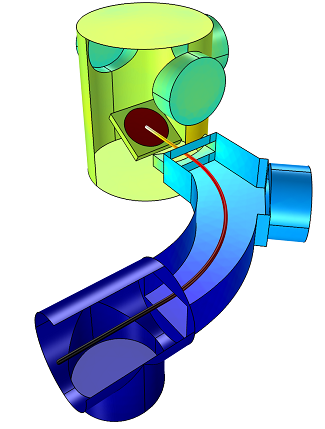
Geometry of the ion-implant vacuum system design. The red circle in the ion-implant cavity represents the wafer and the particle trajectory is also shown.
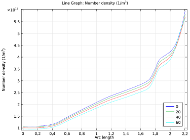
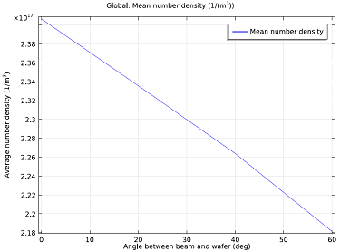
In the model, the wafer is positioned within the main chamber of the vacuum system, and ions are accelerated toward the wafer down the ion-beam path, which is indicated in the figure. It is assumed that 30 sccm of H2 outgasses from the wafer when the beam strikes it. The following results are obtained:
The graphs above show that the number density of the outgassing species increases along the beam path toward the wafer. When the wafer is parallel to the beam, more flux enters the beam line because the line of sight is then parallel to the wafer normal. By altering the angle of the wafer relative to the ion beam, the average number density of the system and the average flux in the corrector can be decreased by 10% over the entire length of the beam.
Upcoming Webinar: Vacuum System Simulations
Interested in learning more about the capabilities of COMSOL Multiphysics for modeling vacuum systems? Attend the upcoming webinar on “Vacuum Systems Simulations” on November 21st. James Ransley, Product Manager at COMSOL, Inc., will be explaining how the Molecular Flow Module can be used for the accurate simulation of vacuum systems, including the modeling of gas flows in molecular flow, transitional flow, and slip flow regimes. Can’t make the live event on November 21st? Check back here or on the registration page to watch the archived webinar.
Model Download
- Download the Molecular Flow in an Ion-Implant Vacuum System model that will be used in a live demonstration during the webinar.


Comments (0)