
In this blog post, guest author Qinghua Lei discusses a modeling framework for analyzing cyclic hydrogen pressurization of an LRC embedded in a fractured rock mass.
Underground hydrogen storage is becoming essential for the global energy transition. Lined rock caverns (LRCs) provide a flexible and geographically adaptable solution, but their safety depends on complex interactions between hydrogen gas, structural linings, and fractured rock masses. Understanding these coupled effects requires advanced numerical modeling. In this blog post, we demonstrate how the COMSOL Multiphysics® software can be used to model LRC behavior during hydrogen pressurization.
Why Use COMSOL Multiphysics® for LRC Hydrogen Storage Modeling?
Modeling lined rock caverns for hydrogen storage presents significant computational challenges. The system involves multiple interacting materials (hydrogen gas, steel, reinforced concrete, and fractured rock), each governed by distinct physical behavior. The surrounding rock mass contains numerous preexisting fractures, introducing pronounced geometric discontinuities and constitutive nonlinearities that strongly influence the system’s response. Deformation of the fractured rock mass interacts closely with the cavern structure, governing stress redistribution and overall system stability. Under high-pressure hydrogen exposure, the steel lining may be susceptible to embrittlement, while the concrete lining may develop cracking that redistributes stresses and influences the deformation of the steel lining. These tightly coupled processes span multiple spatial and temporal scales, making realistic analysis a demanding multiphysics problem.
COMSOL Multiphysics® is well suited for solving such multiphysics problems due to its exceptional capabilities for:
- Simultaneously solving fully coupled multiphysics equations, enabling direct interactions between mechanical, hydraulic, and transport processes
- Defining model parameters as functions of other field variables, enabling indirect couplings such as stress-dependent material properties or damage-driven stiffness evolution
- Explicitly representing discrete fractures within rock masses and resolving nonlinear hydromechanical processes within complex fracture networks
- Handling multiple interacting materials within a unified framework, supported by an extensive library of built-in constitutive models as well as flexible user-defined material formulations
- Implementing custom governing equations and application-specific constitutive models, enabling advanced formulations such as hydrogen embrittlement models to be directly incorporated into the analysis
Below, we discuss the process for building numerical models in COMSOL Multiphysics® for LRC analysis and give a simulation example.
Overview of Modeling Steps
When using COMSOL Multiphysics®, there are three key simulation steps:
- Generating the geometry and mesh
- Coupling parameters and implementing material properties, boundary conditions, etc.
- Calculating the solution
Let’s go over these steps in more detail.
Geometry and Mesh
First, the model geometry is constructed following a multiscale strategy. On the large scale (Figure 1a), a two-dimensional domain is defined to represent a horizontal cross section of the lined rock cavern embedded within a fractured rock mass. The cavern geometry, including the steel lining, reinforced concrete layer, and surrounding shotcrete, can be created directly in COMSOL Multiphysics® or imported from CAD software. Discrete fracture networks are geometrically represented as line segments within the rock domain and can be generated in COMSOL® or using external tools such as MATLAB® or CAD software and then exported as DXF™ files for direct import into COMSOL®. On the small scale, a dedicated model of the steel lining is constructed to resolve hydrogen diffusion and embrittlement processes. The two models are coupled at the steel–concrete interface by enforcing displacement compatibility, enabling consistent interaction between structural deformation and material degradation.
Once the geometry is defined or imported, the large-scale domain is discretized using an unstructured mesh of triangular finite elements generated via Delaunay tessellation (Figure 2). Mesh refinement is applied near the cavern boundary and around fracture intersections to accurately resolve stress concentrations and damage evolution. To represent natural fractures, joint elements between neighboring finite elements are implemented, enabling explicit analysis of nonlinear fracture slip and opening within the rock mass. Thin structural components such as the steel lining and shotcrete layer are modeled using interface elements in the large-scale model in order to maintain computational efficiency. In the small-scale model, however, the steel lining thickness is explicitly represented (Figure 1b) and discretized using solid elements to resolve hydrogen diffusion and embrittlement processes across the thickness. This multiscale discretization strategy makes it possible for the global structural response to be captured efficiently while locally resolving material degradation mechanisms within the steel lining.
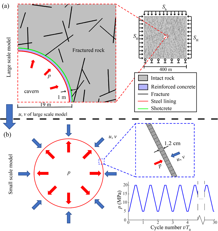 Figure 1. A schematic showing the model design and boundary condition of the multiscale model, including (a) a large-scale model representing an LRC situated in a fractured rock mass and (b) a small-scale model capturing the response of the steel lining subject to cyclic internal pressurization and boundary displacement constraints, as well as hydrogen diffusion. The dimensions and scales shown follow the model configuration adopted in our previous study (Ref. 1) and are presented here to illustrate the model setup strategy. The actual model configuration may vary depending on specific applications and site conditions.
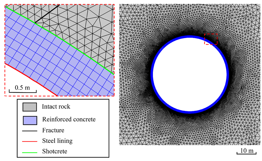 Figure 2. Mesh discretization for the LRC model (Ref. 2). The reinforced concrete layer is discretized using structured quadrilateral elements, while the rock matrix is discretized using unstructured triangular elements. Steel lining and shotcrete are discretized using line elements, whereas fractures are discretized using joint elements.
Interfaces and Couplings
We use the Solid Mechanics interface in COMSOL Multiphysics® to simulate deformation of the fractured rock mass, concrete lining, and steel components under internal hydrogen pressurization. The rock matrix is modeled using a scalar damage formulation to capture crack initiation and propagation, while discrete fractures are implemented as joint elements with nonlinear normal and shear constitutive relations to represent fracture slip and opening.
The reinforced concrete lining is modeled using the Mazars’ damage model, available in COMSOL®, which captures tensile cracking and progressive stiffness degradation. The influence of reinforcement is incorporated through an enhanced elastic modulus and residual strength parameters, consistent with the adopted concrete class.
In the large-scale model, the steel lining is represented using interface elements due to its thin geometry. Its mechanical behavior follows an elastoplastic constitutive law with exponential hardening. To capture hydrogen embrittlement effects, a separate small-scale model explicitly represents the steel lining thickness using solid elements. In this model, a customized interface is developed with the Physics Builder in COMSOL® to simulate the hydrogen diffusion across the lining while accounting for the coupling with solid mechanics. The mechanical behavior of steel is coupled to hydrogen concentration by defining the yield stress as a concentration-dependent variable, enabling analysis of hydrogen-induced strength degradation.
When pore pressure effects in the fractured rock mass are considered, the Darcy’s Law interface in the Subsurface Flow Module is incorporated to simulate fluid flow within the rock matrix and fractures. The Poroelasticity coupling can be activated to achieve direct coupling between mechanical deformation and pore pressure evolution. In this case, hydraulic properties such as permeability or fracture aperture may be defined as stress-dependent variables, enabling indirect hydromechanical coupling consistent with our previous modeling framework.
Material properties and constitutive equations are defined separately for the rock matrix, fractures, concrete, and steel. Direct multiphysics coupling ensures consistent interaction between deformation and hydrogen transport (and pore pressure when activated), while additional indirect couplings are introduced by defining model parameters as functions of evolving field variables such as stress, damage, or hydrogen concentration. Mechanical boundary conditions include in situ stresses applied at the outer rock boundary and internal hydrogen pressure applied at the cavern wall.
Calculating the Solution
The analysis is performed in two stages: In the first stage, the large-scale model is brought to equilibrium under the prescribed in situ stresses using a ramped loading procedure. In the second stage, hydrogen pressurization is applied at the cavern boundary, either monotonically or cyclically, to simulate storage operation. The resulting displacement field from the large-scale model is imposed on the small-scale steel model, where hydrogen diffusion and concentration-dependent mechanical degradation are solved in a time-dependent manner. Nonlinear solution schemes are used to resolve fracture reactivation, damage evolution, and plasticity.
LRC Simulation Example
We apply the multiscale model to simulate cyclic hydrogen pressurization of an LRC embedded in a fractured rock mass (Ref. 1). The large-scale modeling results show cyclic radial displacement of the concrete lining and progressive damage development in both concrete and surrounding rock (Figure 3). Damage localizes primarily in tensile regions and near fracture intersections (Refs. 1–2), highlighting the strong control of fracture distribution in rock on the LRC’s structural response (Figure 4).
The small-scale model captures hydrogen diffusion and embrittlement within the steel lining (Figure 5) (Ref. 1). Hydrogen concentration increases from the inner surface and evolves over loading cycles, leading to local strength degradation that correlates with stress concentration zones. These results demonstrate the coupled interaction between cyclic pressurization, fracture reactivation, stress redistribution, and hydrogen-induced degradation across scales.
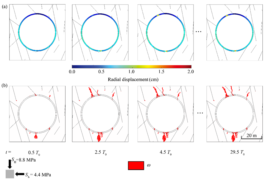 Figure 3. Simulation results (Ref. 1) showing the distribution and evolution of (a) radial displacement in the concrete lining and (b) damage development in the concrete and surrounding rock over multiple hydrogen pressurization cycles (cycle period T0 = 24 h).
Figure 4. Simulation results (Ref. 1) showing the distribution of damage and local maximum principal stress in the vicinity of the LRC during cyclic hydrogen gas pressurization (cycle period T0 = 24 h).
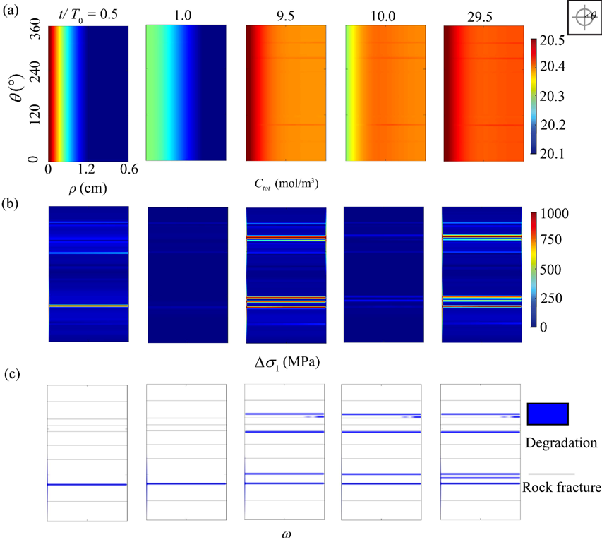 Figure 5. Simulation results (Ref. 1) showing the spatial distribution of (a) hydrogen concentration, (b) maximum principal stress variation, and (c) strength degradation in the steel lining at different loading stages.
In addition, the framework has been extended to include hydromechanical coupling in the fractured rock mass (Ref. 3) and time-dependent rock creep (Ref. 4). These extensions enable us to evaluate how fluid pressure diffusion and viscoelastic deformation in the surrounding rock mass influence the LRC’s long-term performance.
References
- C. Zhao et al., “Modelling lined rock caverns subject to hydrogen embrittlement and cyclic pressurisation in fractured rock masses,” International Journal of Hydrogen Energy, 2025; 152: 150027.
- C. Zhao, Q. Lei, Z. Zhang, “Impact of fracture networks on the structural deformation of lined rock caverns under high internal gas pressure,” Underground Space, 2025; 21: 252-269.
- C. Zhao, Z. Zhang, Q. Lei, “Coupled hydro-mechanical simulation of the interaction between adjacent lined rock caverns subject to internal gas pressurisation,” Geomechanics for Energy and the Environment, vol. 43, 2025: 100701.
- C. Zhao et al., “Influence of rock creep on the performance of lined caverns under cyclic pressurization and hydrogen embrittlement,” International Journal of Rock Mechanics and Mining Sciences, vol. 199, 2026; 106401.
About the Author
Qinghua Lei is an associate professor at Uppsala University, Sweden. He earned his BSc (2009) and MSc (2012) in civil engineering from Tongji University, China, and his PhD (2016) in rock mechanics from Imperial College London, UK. He worked as a postdoctoral researcher in fluid mechanics at Imperial College London (2016–2018) and later as a senior researcher and lecturer in engineering geology at ETH Zurich, Switzerland (2018–2023). He is the recipient of the 2025 ERC Consolidator Grant, 2024 Chin-Fu Tsang Coupled Processes Award, 2019 Rocha Medal, 2016 NGW Cook PhD Dissertation Award, and 2015 Rock Mechanics Research Award. He is a fellow of the Young Academy of Europe. His research interests include rock mechanics, hydrogeology, geophysics, natural hazards, and geotechnical engineering.
MATLAB is a registered trademark of The MathWorks, Inc. Autodesk, the Autodesk logo, AutoCAD, and DXF are registered trademarks or trademarks of Autodesk, Inc., and/or its subsidiaries and/or affiliates in the USA and/or other countries.


Comments (0)