

Magnetic bearings are used in many industrial applications, including power generation, petroleum refinement, turbomachinery, pumps, and flywheel energy storage systems. Unlike mechanical bearings, these types of bearings support moving loads without physical contact through magnetic levitation. Valued for their frictionless operation and ability to run without lubrication, magnetic bearings are a low-maintenance alternative to mechanical bearings with a longer lifespan. Learn how to calculate design parameters like magnetic forces, torque, and magnetic stiffness using the COMSOL Multiphysics® software.
Types of Magnetic Bearings
Based on their operation, magnetic bearings can be classified into one of two groups: active magnetic bearings (AMBs) or passive magnetic bearings (PMBs). AMBs function through an attractive force between a ferromagnetic material and electromagnets (coil and core). PMBs function through a repulsive force between the permanent magnets (PMs) and/or a conducting surface and PMs.
Active Magnetic Bearings
Active magnetic bearings consist of a stationary part — the stator — that contains the electromagnets and the position sensors, and a rotating part — the rotor — that moves with the shaft. Under normal operating conditions, the rotor is ideally centered with an equal gap around the stator. However, in perturbed situations, the rotor’s position is controlled using a closed-loop feedback system. The change in rotor position is measured by the sensor, which is then passed to the digital controller. After processing the data, the controller sends the signals to the power amplifier. The amplifier readjusts the currents in the electromagnets to push the rotor back to its original position. To readjust the rotor, it is important for designers to know the magnetic force at various offset rotor positions as well as the corresponding currents.
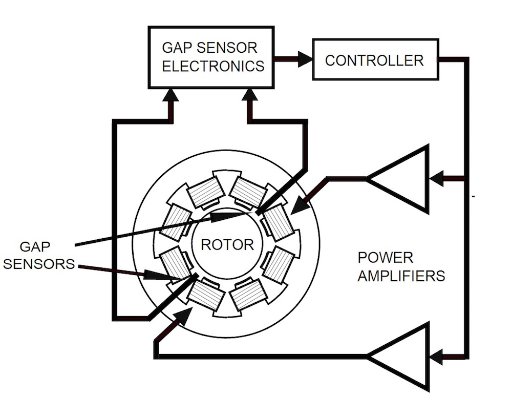
A schematic depicting the components of AMBs. Image is in the public domain, via Wikimedia Commons.
AMBs are advantageous due to their active control of the rotor position, but this means a higher cost for the electronic circuit as well as greater operational costs. The operational costs can, of course, be reduced by optimizing the design of the electromagnets so that less power is needed to run them. COMSOL Multiphysics is a helpful tool in this optimization process.
The most appropriate way to simulate AMBs, including the stator and the rotor, is with the Rotating Machinery, Magnetic interface in the AC/DC Module. The modeling process is very similar to that of an electric generator or motor, as illustrated in our Generator in 2D tutorial. For general guidelines, you can refer to a previous blog post: How to Model Rotating Machinery in 3D.
Using the Magnetic Fields interface, you can model PMs as well as conducting coils (single-turn or multiturn coils). However, you cannot model the induced currents due to rotations. If the induced currents can be neglected, you can set up the model in the stationary or frequency domain and add a parametric sweep study for various rotor positions, computing the magnetic force or torque.
Passive Magnetic Bearings
Passive magnetic bearings use permanent magnets and do not require sensor and control circuitry or input power. The constant air gap is maintained by the magnetic repulsion force between the opposite poles of PMs, as demonstrated in a permanent magnet bearing, or by the electrodynamic suspension (EDS) between the PMs and the rotating conducting disc or shaft, as illustrated by an electrodynamic bearing. The geometry and simulation results for the passive magnetic bearing using PMs is shown below.


Left: Geometry of an axial magnetic bearing using permanent magnets. The magnetization direction of the permanent magnets is depicted by black arrows. Right: The results plot showing the magnetic flux density (arrow plot) and the surface plot of the magnetic flux density norm.
Electrodynamic Bearings
When rotating in a magnetic field produced by a PM, an electrically conducting rotor induces eddy currents on the conducting rotor. These eddy currents, in turn, generate a magnetic field that opposes the magnetic fields by the magnets and induces a repulsive force between the rotating conductor and the stationary PMs. The displacement of the rotor is always balanced by this repulsive magnetic force. Thus, the rotor is rotating at the center with a uniform gap.
Electrodynamic bearings can be further classified as radial electrodynamic bearings and axial electrodynamic bearings. This is based upon whether the magnetic flux is parallel to the rotor axis or perpendicular to the rotor axis, respectively.
Radial Electrodynamic Bearing
A radial electrodynamic bearing consists of a conducting cylinder affixed to a rotating shaft. The components of the PMs are stacked in between the iron rings, such that the radially inward or outward magnetic flux — with reference to the shaft axis — is created in the air gap between the stator and rotor. The Electrodynamic Bearing tutorial, available in our Application Gallery, is solved using the Magnetic and Electric Fields interface. The magnetic forces are computed for various offset positions.

Left: The 3D geometry of a radial electrodynamic bearing. Right: Radial electrodynamic bearing depicting the magnetic flux density in the stator (iron and magnets) and the eddy currents (grayscale) in the conducting rotor for the x-axis offset position of 1.5 mm.
Axial Electrodynamic Bearing
The cross-sectional cut configuration for an axial electrodynamic bearing is shown below. The conducting disc is attached to the rotor and the magnetic material (iron yoke) is used to guide the magnetic fields of the PMs, such that the magnetic flux lines are parallel to the rotor axis. This is where the term axial electrodynamic bearing comes from.
In this design, the magnetic flux path is very effective with a relatively small air gap. The tutorial model is available to download from the Application Gallery.


Left: Cross-sectional cut of an axial electrodynamic bearing. Right: An axial electrodynamic bearing showing the magnetic flux density in the stator and the eddy currents in the conducting rotor. An arrow plot of the magnetic flux density in the stator and the eddy currents in the rotor are also shown.
Both electrodynamic bearing examples discussed above are modeled in COMSOL Multiphysics using the Magnetic and Electric Fields interface. In both cases, the Velocity (Lorentz term) feature is used to prescribe the rotational velocity. By using this approach, you do not need to use the Moving Mesh interface to account for the rotation of the rotor.
Note that the Velocity (Lorentz Term) feature can only be used when the moving domain does not contain prescribed magnetic sources like coils or permanent magnets that move along with the material. The moving domains must also be invariant in the direction of motion. For instance, the Velocity (Lorentz Term) feature can be used to model conductive homogeneous spinning disks. Some examples include magnetic brakes, an electrodynamic bearing, a homopolar generator, magnets over a moving infinite homogeneous plane (such as a falling magnet through a copper tube or maglev trains), and a flow of homogeneous conducting fluid past a magnet (such as liquid metal pumps or hall generators/thrusters).
Note: The Lorentz term accurately accounts for induction in a moving domain caused by stationary magnetic sources, provided the moving domain (including its material properties) does not change in the direction of motion. In addition, induction may be caused by temporal changes to either the strength of the stationary sources or a changing velocity. The Lorentz term does not incorporate the effect of such temporal changes.
Magnetic Force/Torque
In COMSOL Multiphysics, there are two available methods for calculating electromagnetic forces and torques. The most general method is the Maxwell stress tensor method, which is used by the Force Calculation feature in the Magnetic Fields interface; the Magnetic Fields, No Currents interface; the Magnetic and Electric Fields interface; and the Rotating Machinery, Magnetic interface.
For instance, by adding this feature, the spatial component of the magnetic forces (mf.Forcex_0, mf.Forcey_0, mf.Forcez_0) and the axial torque ( mf.Tax_0) in the Magnetic Fields interface are available for postprocessing. The Force Calculation feature simply integrates the Maxwell stresses, evaluated just outside of the selected domain (or domains) and over the entire outer boundary of the domain selection, which should be a group of domains moving together (a single mechanical body). Since this method is based on surface integration, the computed force is sensitive to mesh size. It is important when using this method to always perform a mesh refinement study to correctly compute the force or torque.
The force calculation will not be correct if the domain applying the Force Calculation feature is touching an external boundary, a periodic boundary, and an identity pair. Furthermore, to compute the force on a magnet attached to a ferromagnetic surface, contact boundaries must have a thin low permeability gap (thin low permittivity gap for the electrostatic equivalent) assigned, as the Maxwell stresses should be evaluated in air rather than in the ferromagnetic (dielectric) material.
The second method — the Lorentz force method — works only in special cases for computing the magnetic force on nonmagnetic, current-carrying domains. The Lorentz force is defined as F = J × B, where J is the current density and B is the magnetic flux density. The Lorentz force is very accurate for force calculations in electrically conducting domains as it is evaluated in the volume rather than on boundaries. Therefore, whenever possible, the Lorentz force method is preferred over the Maxwell stress tensor method.
In addition to those built-in methods referenced above, the magnetic force and torque can also be calculated using the virtual work method, or the principle of virtual displacement. In this technique, the force is calculated by studying the effect of a small displacement on electromagnetic energy. The virtual work method can be employed by using the features for deformed mesh and sensitivity analysis in COMSOL Multiphysics.
Magnetic Stiffness
In solid mechanics, stiffness is the rigidity of an object — the extent to which the object resists deformation in response to an applied force. Similarly, in magnetic bearing applications, the parameter is defined as the magnetic stiffness, and it is the negative of the derivatives of the total magnetic force with respect to position. If the magnetic force is Fz, the magnetic stiffness with respect to position z is given by:
A tutorial model illustrates this method for computing the magnetic stiffness in an axial magnetic bearing. This example, however, is limited to 2D axisymmetry. Therefore, the magnetic stiffness in the x– and y-directions cannot be evaluated. To evaluate the magnetic stiffness in all directions, you would need to model the problem in 3D. Here, we will create a 3D version of the same axial magnetic bearing discussed above and determine the stiffness kx. You can download this example tutorial from our Application Gallery.
This approach primarily involves the use of the Magnetic Fields, Deformed Geometry, and Sensitivity interfaces. As in the 2D model, the Magnetic Fields interface is used. The magnets are modeled using the Ampère’s Law feature with the constitutive relation set to a remanent flux density of 1[T]. The Force Calculation feature is added to the inner magnets only and the geometry is parameterized such that the position of the inner magnets has an offset X0 in the x-direction. The parameter X0 will later be used for a parametric sweep. In addition, the Deformed Geometry interface will be used to analyze the sensitivity of the force to an additional (virtual) mesh displacement dX in the same direction. Only a quarter of the geometry will be used here to compute the magnetic stiffness in the x-direction.
In this configuration, note that only the x-axis forces are correctly computed. Due to the symmetry, the force in the y– and z-directions should be zero. However, due to the fact that only a quarter of the geometry is modeled, the computed force will be quite large. The stiffness in the y-direction can be computed similarly by analyzing a quarter model cut symmetric to the yz– and xy-planes.


Left: The quarter 3D model of an axial magnetic bearing for stiffness calculation. Right: The magnetic flux density norm and the magnetic flux density arrow plot in a half model. The results are plotted using a Mirror 3D data set at the xy-plane.
The Deformed Geometry interface is solved everywhere except in the infinite element domain region. To solve for this region, begin by adding a Free Deformation node on the air region around the magnets. Similarly, you can add a prescribed deformation of dX on the domains of the inner magnets along the x-axis. Finally, add two Prescribed Mesh Displacement nodes for the inner magnet boundaries and the symmetry cut plane boundaries, as illustrated below.

Settings for prescribed deformation on the inner magnets’ domains.

Settings for prescribed mesh displacement on the inner magnets’ boundaries.

Settings for prescribed mesh displacement on the symmetry cut boundaries.
In the Sensitivity interface, add the Global Objective feature and specify the total force in the x-direction (i.e., 4*mf.Forcex_0) in the objective expression under the Global Objective settings. Here, mf.Forcex_0 is the x-component of the Maxwell stress tensor force that is being calculated by the Force Calculation feature in the Magnetic Fields interface. Similarly, add the global control variable dX, as shown below.

Settings for the global objective (left) and the global control variables (right).
Since the Sensitivity (and Optimization) study cannot be combined with a Parametric Sweep study node, the model must be solved in two separate studies. The first study will include the Sensitivity solver and the Stationary solver. The second study will then have a Parametric Sweep study, but will use Study 1 as a study reference. Perform the parametric sweep over a parameter X0 using the interval of range(0,1.5/20,1.5), with the settings shown below.


Left: Settings for the Stationary study for sensitivity analysis. Right: Settings for the Parametric Sweep study using Study 1 as a reference.
The magnetic force in the x-axis and the magnetic stiffness in the x-direction are plotted as 1D global plots.

Settings for the magnetic force plot (left) and the magnetic stiffness (right).


Left: The electromagnetic force x-component as a function of offset in the x-axis. Right: The magnetic stiffness kxx as a function of offset in the x-axis.
Summary
Here, we have discussed several types of magnetic bearings that can be modeled in COMSOL Multiphysics using interfaces available in the AC/DC Module. Simulation provides a simplified approach to addressing design parameters within these types of bearings, helping to optimize their performance as well as their lifespan.
In the next blog post in this series, we will focus on how COMSOL Multiphysics can be used to model magnetic gears. Stay tuned!
Editor’s note: This blog post was updated on 09/05/2017.


Comments (7)
Fedai ?nan?r
December 30, 2015Good work. cong. Please Could you kindly upload example file of pdf tutorial.
Regards
Nirmal Paudel
December 30, 2015 COMSOL EmployeeThe example model is available here:
http://www.comsol.com/model/magnetic-stiffness-of-an-axial-magnetic-bearing-in-3d-27761
Please contact COMSOL Support if you need further assistance.
Best Regards,
Nirmal
SUDIPTA SAHA
February 4, 2017could you upload full simulation guidelines for radial active magnetic bearings?
Caty Fairclough
February 6, 2017Hello Sudipta,
Thanks for your comment! For your question, I’d suggest contacting our support team.
Online support center: https://www.comsol.com/support
Email: support@comsol.com
Best,
Caty
Philip Swan
August 8, 2019I also would like to see a post that provides a clear and complete explanation of how to model an active magnetic bearing. It should include the position sensors and control electronics. From the simulation it should be possible to determine how much magnetic friction exists and how much current is being drawn by each electromagnet as a function of RPM, load, perturbation, time for a given set of design parameters.
acepik .
May 17, 2021Hi all
To calculate force in x-and z- displacement the mfnc.Forcez_0 is used on halbach arrayed magnets.
If the inner magnet is replaced by magnetic steel (spoke type), still is this formula calculating correct force applied on the whole rotor (inner steel ring and side magnet rings)?
Many thanks and kind regards
Acepik
Prasanna Kumar Routray
March 22, 2024Nirmal, nice information. However, the model is not available to download.
Regards,