

Imagine commuting home from work in a dark, dreary subway station. Catching a rare glimpse of natural sunlight could brighten your day and make the ride home much more bearable, but how? With light pipes, natural light can be distributed in otherwise dark areas without any electricity. In this blog post, we explore these simple and elegant devices and show how they can be analyzed in greater detail through simulation.
Transparent Light Pipes Provide Natural Illumination
Light pipes, also known as light tubes, are structures used to transport light between different areas. Large spaces can be illuminated by selectively leaking radiation from the sides of pipes. Light tubes save energy and provide natural light, heat insulation, and flexibility. These types of tubes are an optimal source of natural light in underground areas, like the subway station mentioned in the example above. They are also ideal in prisons and areas with restricted access, where light is needed but windows and openings are risky.
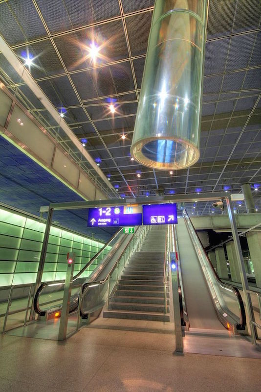
Light tubes are used to illuminate underground areas, like the Potsdamer Platz train station in Berlin. (By Till Krech. Licensed under the Creative Commons Attributions 2.0 Generic license, via Wikimedia Commons.)
You might also see light tubes in a residential setting. For instance, because this light source doesn’t use electricity, it’s a safe lighting method for wet areas such as bathrooms and pools. Some electronic devices even use small light tubes to illuminate buttons instead of electricity. They can also be used to help those suffering from seasonal affective disorder (SAD) by providing natural sunlight throughout the year.
In addition to transporting light to hard-to-reach areas, light pipes can also be used to create a uniform light source or to integrate several different light sources. Because light is often reflected many times within the pipe before reaching the end, it tends to be distributed uniformly at the exit, no matter how it enters the pipe. Structures that are used for such purposes are also called homogenizing rods.
There are two main types of light tubes:
- Hollow tubes lined with a reflective coating
- Solid transparent light pipes that contain light through a phenomenon called total internal reflection
We’ll discuss the second type here.
Guiding the Light by Means of Total Internal Reflection
Total internal reflection occurs when the light that reaches a boundary between two different media is completely reflected. For this phenomenon to occur, light must be traveling from a more optically dense medium to one that is less optically dense. In this context, “optical density” refers to the medium’s refractive index n, which is the ratio of the speed of light in vacuum to the speed of light in the medium. For example, water has a greater refractive index than air, so it is possible for total internal reflection to occur when rays from an underwater source arrive at the surface.
In addition, for total internal reflection to occur, the angle of incidence must be greater than the critical angle. The angle of incidence is the angle between the ray of light propagating to the surface (the incident ray) and the normal, or the line perpendicular to the surface. It is indicated by \theta_i in the following diagram.
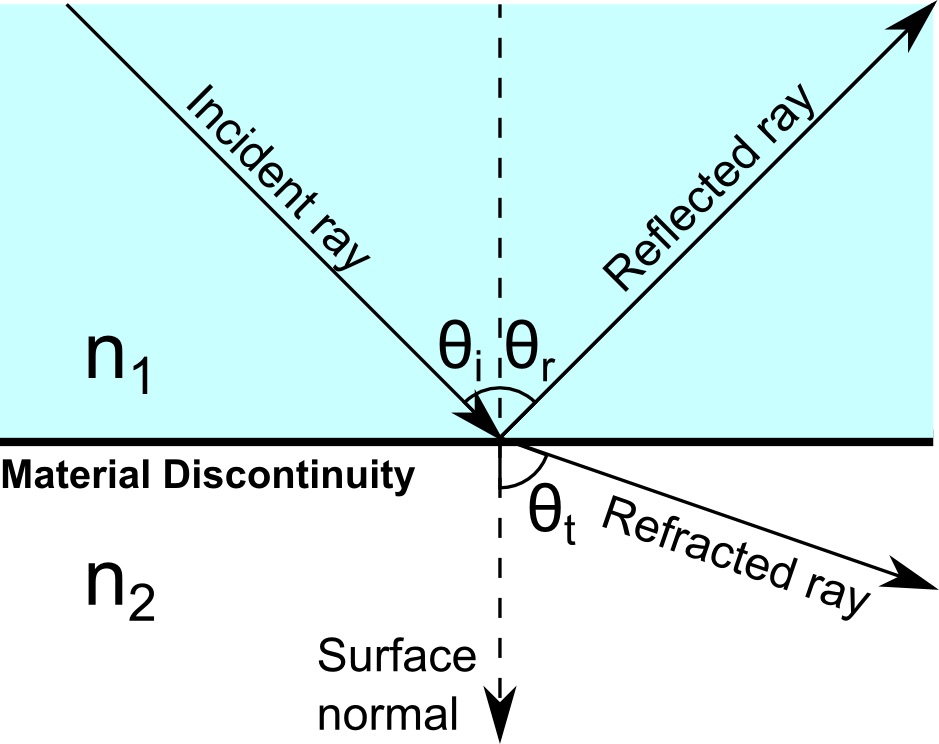
Incident, reflected, and refracted light rays at a boundary between two media.
Similarly, the angle of refraction is the angle between the refracted ray and the normal. It is given by \theta_t in the diagram. Because we’re assuming that n_2 < n_1, the angle of refraction is greater than the angle of incidence. The critical angle is the angle of incidence for which the angle of refraction equals 90°. As the angle of incidence is increased closer to the critical angle, the intensity of the refracted light approaches zero. For an angle larger than this, no real value of the angle of refraction exists. Then the ray is completely reflected at the boundary and thus total internal reflection occurs.
We can use this phenomenon to effectively trap light in a solid transparent tube surrounded by air. If the tube has a greater refractive index than the air, it is possible for light to be contained within the tube by total internal reflection. For this to happen reliably, light should only reach the outer surfaces of the tube at large angles of incidence, nearly parallel to the surfaces. If light reaches the surface at an angle of incidence that is smaller than the critical angle, then refraction will occur and some of the light will leak out of the pipe walls, as illustrated by the following diagram.
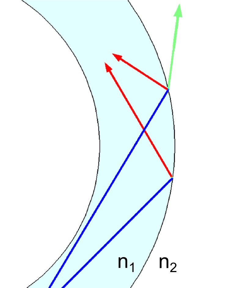
If incident rays (blue) reach the pipe wall at large angles of incidence, only reflected rays (red) will be produced. If the angle of incidence is too small, refracted rays (green) may also be released.
We can analyze the performance of a transparent light pipe using COMSOL Multiphysics simulation software and the Ray Optics Module.
Simulating a Transparent Light Pipe with COMSOL Multiphysics
The Transparent Light Pipe tutorial simulates ray propagation in a bent light pipe with a circular cross section. The pipe is made out of solid poly(methyl methacrylate) or PMMA, which is a transparent thermoplastic material.
If the light pipe changes direction abruptly, it is possible for a large amount of light to reach the surface at angles of incidence less than the critical angle, allowing a significant amount of energy to be lost due to refraction. We can quantify the effect of the shape of the light pipe on its performance by performing a parametric sweep over the radius of curvature of one of the bends in the pipe. First, light rays are released at one end of the pipe with a conical distribution. By applying a Wall node and the Deposited Ray Power subnode at the opposite end, we can measure the transmittance of the light pipe by computing the ratio of the transmitted power to the source power.
Homogenization of an LED source by total internal reflection within a bent light pipe.
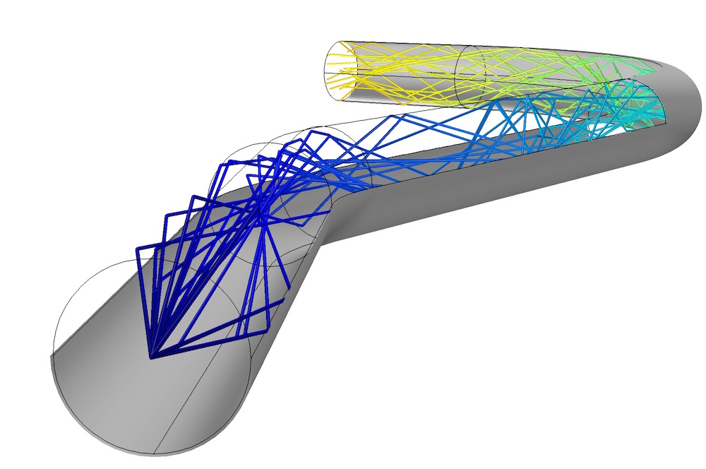
In the following plot, light rays enter the pipe from the left end and propagate toward the right end. As the rays hit the second bend, a large number of refracted rays are released through the pipe walls. The first bend is much more gradual than the second one, so no refracted rays are able to escape there.
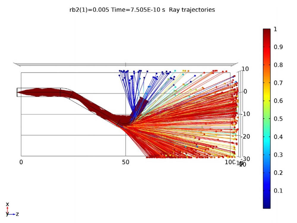
Ray trajectories in the transparent light pipe. The color expression shows the ratio of the intensity of each refracted ray to the corresponding incident ray, with larger values indicating greater losses.
The transmittance of the pipe is calculated to be about 100% when the radius of curvature reaches its maximum simulated size of 20 millimeters.
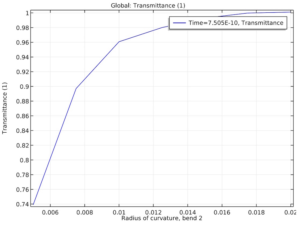
The transmittance of the light is plotted as a function of the radius of curvature in one of the pipe bends.
We can use the results from this simulation to determine that a larger radius of curvature in the pipe’s bends will lead to more reliable transmission of light. Depending on the application, the benefit of a large pipe bend radius may be offset by the need to fit the pipe into a confined or hard-to-reach area. Through simulation, we can consider all of these factors in order to optimize the usage of light pipes in many applications.
Try It Yourself
- Download the Transparent Light Pipe tutorial along with step-by-step instructions on how to build it yourself.

Comments (1)
mona aghaee
January 29, 2018Hi,
I have problem modeling radiation heat transfer in a slab. A constant radiation hits an slab and part of that id transferred through the slab, part is absorbed within the slab and part is reflected. How should I model this? There are a lot of complicated models answered but none of them works for this. where and how could i enter transmisivity and reflectivity of the slab? Could you please give some information?
Thanks
Mona