

From home HVAC systems to spacecraft ejectors, diffusers find use in all kinds of applications. For example, diffusers are often used in supersonic aircraft like ramjets to slow down fluid flow and increase static pressure. To design transonic diffusers for supersonic applications, engineers must account for factors like high-speed turbulent flow and shock waves. As this benchmark model illustrates, these complex phenomena can be accurately analyzed using the COMSOL® software.
Slowing Supersonic Speeds with Transonic Diffusers
Diffusers have two main purposes:
- Slowing down fluid flow
- Increasing static pressure
These abilities are useful for various applications, including helping HVAC systems evenly distribute air, reducing pressure losses in supersonic ejectors, minimizing turbulence in centrifugal pumps, and reducing drag in race cars.
Diffusers are important components in supersonic aircraft propulsion systems. For instance, ramjets (also called “flying stovepipes”) are a type of air-breathing jet engine that use diffusers as inlets. The diffuser slows down the airflow in the engine to subsonic speeds so that it doesn’t extinguish the burner and also helps minimize flow losses. By increasing the pressure, the diffuser also helps enhance the performance of the combustor, which in turn makes the aircraft more fuel efficient.
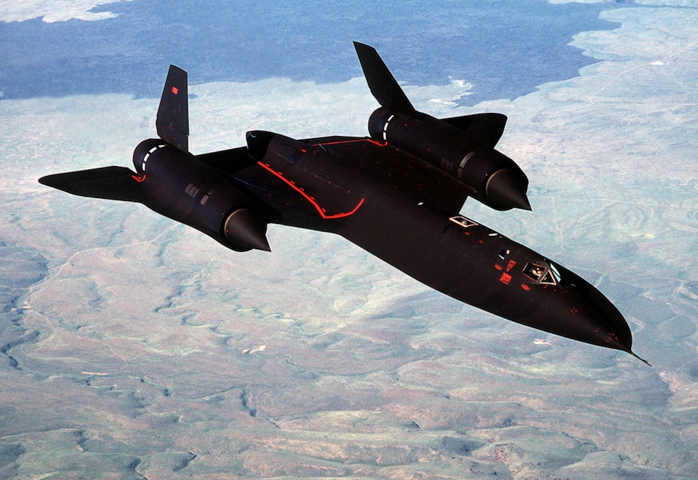
Ramjets can be found in various supersonic aircraft, such as the SR-71 Blackbird featured above. Image in public domain, via Wikimedia Commons.
An optimized diffuser makes for a better supersonic aircraft engine, but designing this component can be a challenge, as it involves unsteady fluctuations, high speeds, shock waves, and flow separation. To take these factors into account and design optimized transonic diffusers, engineers can use the COMSOL Multiphysics® software and add-on CFD Module, as discussed in this benchmark example.
Modeling a Transonic Diffuser with the CFD Module
The diffuser in this example uses the geometry from M. Sajben and his team in their benchmark experiments and simulations. In the model, fluid (i.e., air) travels through a convergent-divergent diffuser. Note that this diffuser is transonic with a turbulent flow that starts out as subsonic. As the flow moves through the diffuser, it accelerates to sonic conditions in the throat and supersonic conditions in the diverging part (where the geometry starts to expand).
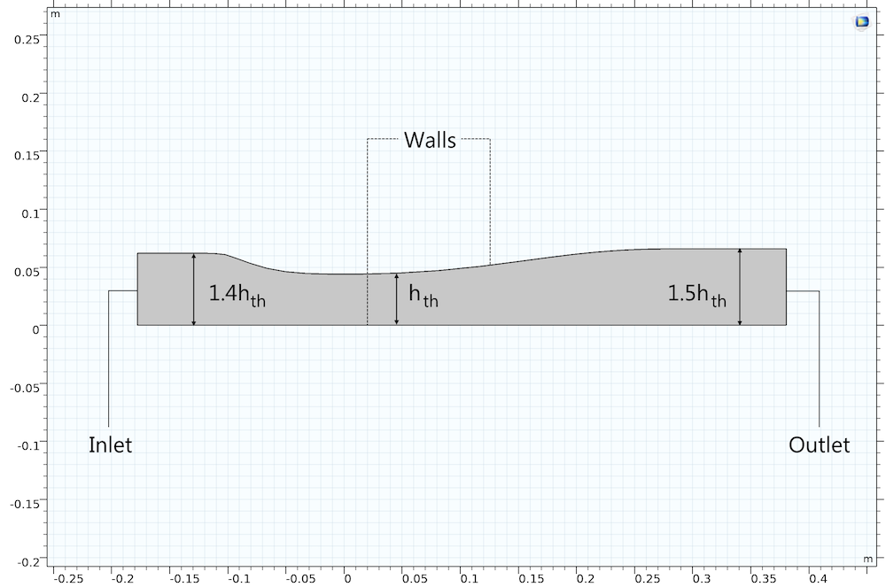
The model geometry of the Sajben diffuser.
Once the flow is supersonic, a shock wave brings it back to subsonic speeds. The wave either causes the flow to separate (a “strong” shock) or stay together (a “weak” shock). This model examines both scenarios.
An outlet pressure of 16.05 psi is applied for the weak shock and 14.10 psi for the strong shock. These pressures are low enough for the flow to become sonic, but not so low that it stays supersonic throughout the diffuser. At the inlet, you can evaluate the flow characteristics and apply a numerically consistent boundary condition. The inlet conditions, such as temperature and pressure, are defined based on their total properties (500 R and 19.58 psi, respectively).
To effectively describe the airflow in the diffuser, the model uses the High Mach Number Flow interface, which is particularly useful for simulating supersonic gas flow. As for the turbulence of the air, it is calculated using the height of the channel and the inlet properties, while the viscosity is computed via the Spalart-Allmaras turbulence model.
Note that this model is highly nonlinear and dependent on the solution procedure. While we don’t go into detail about solving the model in this blog post, you can find step-by-step instructions in the Transonic Flow in a Sajben Diffuser tutorial. With a COMSOL Access account and valid software license, you can also download the MPH file for this benchmark.
Comparing the Simulation Results to Experimental Data
The results show the velocity of the air as it moves through the diffuser for the different outlet pressures. In the two cases, the results are as expected: The air accelerates to supersonic speeds and a shock wave slows the flow back down, with the strong shock causing flow separation.


The flow velocity in a transonic diffuser for a weak (left) and strong (right) shock.
The static pressure on the top wall is normalized by the inlet pressure. For both outlet pressures, the results generally agree with the experimental data, although the shocks in both simulations occur slightly more downstream than they do in the experiments.
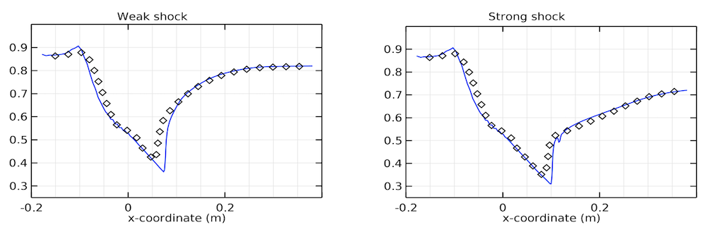
Comparison of the static pressure between the model (lines) and experiment (diamonds) for the two outlet pressures.
The streamwise velocity profile from the strong shock case is plotted at two different positions in the diffuser. Examining the first position shows that flow separation starts in about the same place as in the experiment and has a similar speed. As for the second position, the speed of the air in the center still agrees well with the experiment, but a flow reversal in the model indicates that the separation zone extends slightly farther downstream.
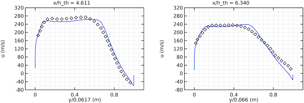
The velocity profiles at two positions in the diffuser. The model results (lines) are compared with experimental data (diamonds).
Overall, the simulation correlates well with experiments, showing that the CFD Module accurately solves for turbulent high-speed flow, including supersonic flows and shock waves. With this functionality, engineers can optimize transonic diffuser designs and enhance propulsion systems for supersonic aircraft.
Next Step
Want to try this benchmark model? Click the button below to head to the Application Gallery, which includes the MPH file and documentation for the transonic diffuser example.


Comments (0)