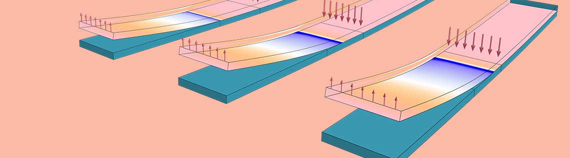

As of COMSOL Multiphysics® version 5.2a, we bring you features designed to enhance your structural mechanics contact modeling. You can, for instance, simulate objects that stick together once they come in contact (adhesion) as well as those that pull apart (decohesion), including full cohesive-zone modeling. Learn how to address each of these scenarios using the new functionality in COMSOL Multiphysics.
Making Things Stick Together: How to Model Adhesion
Whenever you apply compressive forces that press physically separate solids together, mechanical contact at the boundaries deforms the solids such that the touching boundaries conform to each other. If you instead apply tensile forces that pull the domains apart, then there is no contact. This effect can be modeled using traditional contact modeling in COMSOL Multiphysics. If the objects instead stick together, it means that they support a tensile or adhesive force.
It turns out that when modeling forces related to contact and adhesion, special care needs to be taken with respect to what happens to forces acting in the tangential direction. While objects are in contact, there are three possible “tangential states”: frictionless sliding, sliding with friction forces, or sticking due to friction. As an additional complication, there are several processes in which two boundaries will begin sticking together only when some physical condition is fulfilled. It could, for example, be an adhesive material that cures only above a certain temperature and thus only then becomes actively adhesive. All of these phenomena can be represented with the adhesion and decohesion functionality, new as of version 5.2a of the Structural Mechanics Module.
Let’s consider two solid parts that are joined together by a layer of glue (this can be actual glue or something that conceptually behaves like glue). In COMSOL Multiphysics, the key to joining these two boundaries is the new Adhesion subnode, available as a child node to the Contact node in the model tree in the Model Builder.
To use the Adhesion subnode, you must select the option penalty formulation for the contact modeling. This formulation can be viewed as using a stiff, unidirectional spring to model the contact. When the two boundaries press on each other, a virtual thin elastic layer exists between the boundaries. When the “sticking” mode is initiated, the spring is made bidirectional, and it is also given a tangential stiffness. If there is an actual adhesive layer between the two boundaries, you can utilize a stiffness based on real material data. Otherwise, you can use a high stiffness, so that the two boundaries are virtually welded together.
When it comes to describing the onset of adhesion between the two layers, you can choose between four different criteria:
- When a certain contact pressure is exceeded
- When the two boundaries come within a certain distance of one another
- From the very beginning of the analysis
- When a user-defined Boolean expression is fulfilled
Stress and deformation for a sticking cylinder.
To begin, let’s take a look at the above animation. Here, a cylinder is pressed down into a flexible support and its motion is then reversed. The contact is modeled with an adhesion triggered by the contact pressure. When the cylinder moves back up again, it is actually pulling the foundation upward. The bending stress below the cylinder is more or less constant on the way up, since the foundation has to assume the constant curvature of the cylinder. Additionally, you can see the stress concentrations at the transition from the sticking to the nonsticking parts of the boundaries. This effect could, in reality, cause partial decohesion of the adhesive layer — a fact that we will return to at a later point.
The option to enter a user-defined adhesion criterion provides you with a great deal of flexibility in your contact modeling. You can, for instance, model a glue that requires a certain temperature or certain time to cure. Let’s move on to another example that illustrates this.
In the following case, a slider is pulled with constant speed along a larger foundation, while the whole assembly is heated up from the initial room temperature. The criterion for initiation of adhesion is selected so that the temperature at the contact boundary should exceed 365 K. The geometry and boundary conditions are highlighted in the following set of figures, along with the user-defined adhesion criterion.
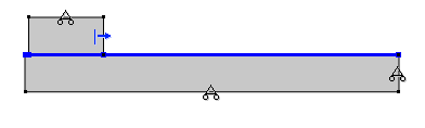
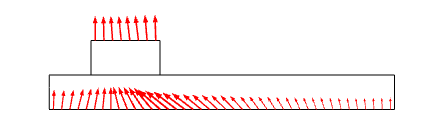
Left: The mechanical boundary conditions (rollers on three boundaries, prescribed horizontal displacement on one side of the slider, and contact between the slider and the foundation). Right: The thermal boundary conditions (convective heat flux on the top of the slider and bottom of the foundation). Thermal contact is modeled between the two parts.
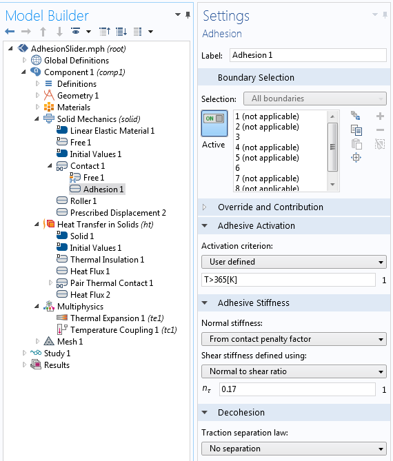
Entering a user-defined adhesion criterion.
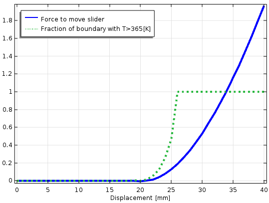
When a time-dependent analysis is performed, the slider moves almost without resistance and as long as the temperature at the contact boundary is below 365 K. Once that temperature has been reached, an elastic bond is created so that a large force is required to further move the slider.
Time-dependent analysis in which the domains are colored by temperature. The green contour is the adhesion temperature at 365 K. The arrow shows the force that is required to move the slider.
Development of shear force, plotted together with the interface temperature.
As an additional note, this simulation includes a Pair Thermal Contact node in the model tree, through which the thermal resistance between the two parts is a function of the contact pressure. The contact pressure increases over time due to the inhibited thermal expansion in the vertical direction. As such, the heat transfer between the two parts is relatively small at the start of the simulation.
Making Things Break Up: How to Model Decohesion
Up to this point, we have discussed how two boundaries are made to stick together. You can, however, also model the opposite situation, where two boundaries are torn apart as soon as the force is large enough. Such behavior is controlled via the Decohesion section of the Adhesion subnode.
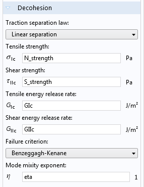
Settings for decohesion.
You can use the new decohesion functionality for simulating either delamination between two layers, or for describing crack growth in a continuous material. In the latter case, the crack path must be known prior to conducting the analysis. The formulation, called a cohesive zone model (CZM), is based on a material model where the following applies:
- The stress in the adhesive layer is a function of the separation distance between the boundaries.
- The behavior of the layer is linearly elastic up to a certain separation distance between the boundaries.
- When the peak elastic deformation has been reached, the stress decreases with further deformation.
- Once a certain energy has been consumed, the bond between the two layers is completely broken.
- If unloaded before the bond is fully broken, the layer is considered to be damaged, thus featuring a reduced elastic stiffness.
In the graph below, the normal stress versus the boundary separation for a pure tension case is shown. The input data required is the maximum stress \sigma_{\textrm{ic}} and the area under the blue curve, which can be interpreted as the energy release rate G_{\textrm{iC}}. The sloping red line is the elastic path, which would be followed during unloading from a partially damaged state.
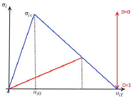
Stress versus boundary separation for the linear separation law.
A similar curve relates the shear stress to the shear deformation. So, for the pure tension and pure shear cases, the decohesion behavior is uniquely defined. For more general cases, a mixed-mode separation law is used. This law essentially provides a weighting of the two basic cases, similar to how an equivalent stress is used for multiaxial stress states in plasticity.
When it comes to the different constitutive laws, you can choose from one of three options. In addition to the linear separation law outlined above, a polynomial law and multiaxial separation law are also available.
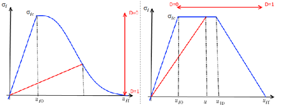
The polynomial and multilinear separation laws, respectively.
To show how you can model decohesion, we’ll use our Mixed-Mode Debonding of a Laminated Composite tutorial model from the Application Library of the Structural Mechanics Module. This example simulates an experimental setup known as a mixed-mode bending (MMB) test. The purpose of the test is to study the delamination of a laminated composite beam. The geometry is such that a well-defined state of mixed tension and shear can be created.
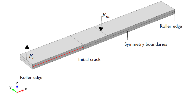
The geometry of the test specimen for the MMB test.
During the test, the initial crack will start growing when the load exceeds a critical value. As the crack begins to grow, the structure will become more flexible so that the force is reduced. This is illustrated in the graph below.
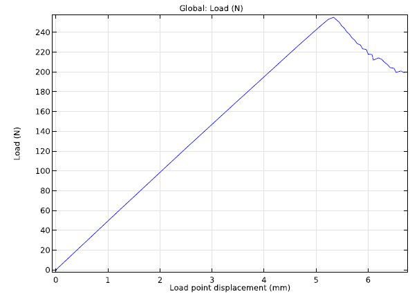
A graph comparing force and displacement at the outer edge of the beam.
The physical experiment, as well as the simulation, must be performed under controlled displacement conditions. Otherwise, unstable crack growth will occur once the peak load is reached.
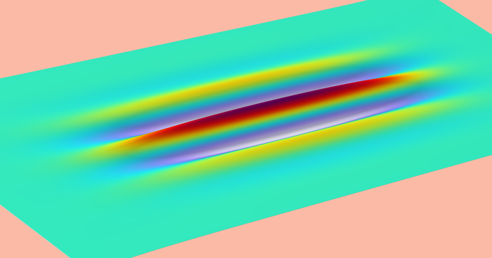
Equivalent stress in the upper layer and forces applied at the outer edge of the beam. The delamination, accompanied by a reduction in load, is clearly visible. The deformations have a true scale.
For this example, we have utilized the option to implement the effects of adhesion from the start of the simulation. Note that the actual bonding process is not part of the simulation. There is, however, a way to combine these two effects.
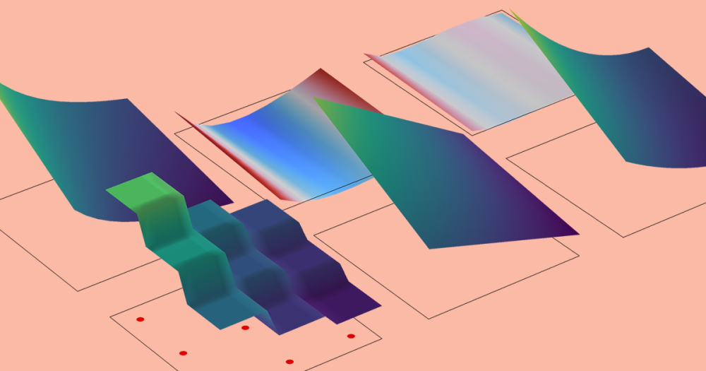
In our first example, very high stresses were visible at the end of the adhesive layer. But what if we chose to add a decohesion rule as well? The final result of such a simulation is depicted below. The extent of the sticking layer is reduced due to some debonding that has occurred. At the turning point, and during part of retracting motion, the results of the two simulations are equivalent. Later on, however, the stresses in the adhesive layer exceed the decohesion limit, causing the contact to be lost.
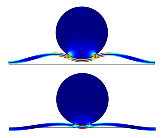
Final state of the simulation after only applying adhesion (top) and when adhesion and decohesion are combined (bottom).
Additional Contact Modeling Scenario: Always in Contact Without Friction
Consider a case where adhesion is active, but you have set the shear stiffness of the adhesive layer to zero. This means that the two boundaries are connected to each other in the normal direction, but will be free to slide in the tangential direction. There are some cases where you could make use of this behavior — modeling bearings is one example.
Two semicylinders, shown in the following animation, are joined in such a way. The larger cylinder has roller conditions that restrict vertical motion and rotation, with an elastic spring that resists horizontal displacement. The smaller cylinder, meanwhile, has a prescribed translation and rotation. At the start of the simulation, the force between the two objects is predominantly tensile. Toward the end of the simulation, the smaller object pushes on the larger object. Throughout the simulation, the tangential force between the two connected boundaries is zero.
Semicylinders that are connected only in the normal direction.
Advance Your Structural Mechanics Contact Modeling in COMSOL Multiphysics®
The functionality for modeling adhesion and decohesion in COMSOL Multiphysics, released in version 5.2a, provides you with several new possibilities for performing high-fidelity structural mechanics simulations. These tools are particularly powerful in the analysis of manufacturing processes in which parts are being joined. Decohesion modeling is also important when studying the maximum load-bearing capacity of structures. By delivering accurate and fast results, this new contact modeling functionality can help foster the development of more efficient and reliable manufacturing processes across a range of industries.
Next Steps
- Watch this video to learn how to create contact pairs when modeling structural contact
- Browse additional applications of structural mechanics modeling here on the COMSOL Blog

Comments (44)
Ehsan Nabiyouni
November 22, 2016Is this feature also available in Shell Physics?
Henrik Sönnerlind
November 23, 2016So far, only in Solid Mechanics.
Henrik Sönnerlind
August 13, 2020 COMSOL EmployeeFrom version 5.5, contact (and thus also adhesion/decohesion) is available also for shells and membranes.
Suresh Seetharam
November 24, 2016Hello Henrik,
Is there a way to insert cohesive elements along mesh boundaries please? I see that this is only possible if we explicitly define interior boundaries where we think the crack might follow.
I ask this question because there is an option for weak contribution on mesh boundaries. And so far I have never used this and I do not know the purpose of this feature. It appears intuitive that it may be possible to define weak form for cohesive model via the weak contribution on mesh boundaries, but then the issue of normals or up-down operators become undefined unlike when we have an explicitly defined interior boundary.
Can you comment on this please?
Thank you,
With best regards,
Suresh
Henrik Sönnerlind
November 28, 2016Hi Suresh,
Using the weak contribution on mesh boundaries is useful when no continuity over the mesh boundaries is assumed, that is when discontinuous shape functions are used.
In the Solid Mechanics interface, the shape functions for the displacements always assume continuity unless an explicit slit condition (such as a Thin Elastic Layer) is used. Since that can only be controlled by boundary selections, there is no way in which you can disconnect all element edges.
Regards,
Henrik
Suresh Seetharam
November 28, 2016Hi Henrik,
Thank you very much.
Your clarification is clear to me.
Regards,
Suresh
Suresh Seetharam
January 23, 2017Hello Henrik,
Two very general questions came to my mind.
1. There is a term “normal to shear ratio” defined as “n_tau=K_tau/Kp” in the manual page 357 and “K_tau” and “Kp” are also used in page 359. Whereas in the COMSOL GUI, there is an option to input “n_tau” as well as “K_tau” and “Kp”, which can cause confusion because either of the two will suffice. Or have I understood it wrongly? I think in Camanho et al. paper they do not have the term n_tau in u_mf?
2. There is no option for decohesion for axisymmetric problems. Is there a particular reason apart from the application it is targeted for please?
Thank you,
Regards,
Suresh
Henrik Sönnerlind
January 24, 2017Hi Suresh,
Unfortunately, I do not fully understand any of your questions.
1. It only the normal stiffness which can be entered in the GUI (either in the Contact node or in the Adhesion node), and then there are two different ways of entering the ratio between normal and shear stiffness.
2. There should be no difference between axisymmetry and 2D or 3D.
Regards,
Henrik
Suresh Seetharam
January 24, 2017Hi Henrik,
Thank you for your kind response. I realize my mistakes, which explains why you did not follow me.
For question no.1, I was mixing up shear and normal stiffness for adhesion with shear and normal strength for decohesion. So I am sorry.
For question no. 2, I realize that unless I select penalty method for contact pressure, adhesion node does not become active. So when looking at the axisymmetric model, by mistake I had left it at Augmented Lagrangian.
Sorry for wasting your time.
Regards,
Suresh
Victor Marcos Meson
June 28, 2017Hello Henrik,
Thanks for this very interesting article. I am considering implementing the decohesion feature to model tensile fracture (mode I). I have limited experience with the solid mechanics module in Comsol. However, I am considering using Comsol, since I am planning to implement multiphysics in the future.
For my case, I would need to model the descending branch of the traction-separation as a multi-linear law (i.e. tri-linear cohesive law), since I am modelling the macroscopic behaviour of a composite reinforced with deformed fibres.
Reading trough the documentation, I could understand that: in the adhesion feature, the descending branch would be defined as a function of the Tensile/Shear energy release rates (GIc, GIIc) and maximum stresses and stiffness.
My question is:
Would I be able to define a tensile energy release rate factor (GIc) dependent on the separation, so that I can implement a multi-linear law for the descending branch of the traction-separation law?
Thanks in advance,
Victor
Henrik Sönnerlind
June 28, 2017Hi Victor,
I think a completely manual implementation of the separation law would be the best alternative for you. Basically you can create some variables of your own, and then either
a) replace expressions in Equation View under Adhesion
or
b) create your own decohesion law by modifying a Thin Elastic Layer.
If you examine the files for version 5.2 in https://www.comsol.com/model/mixed-mode-debonding-of-a-laminated-composite-19961 , you can see how the latter approach was used to implement the same functionality before we added the built-in decohesion laws.
Shashank Tiwari
July 3, 2017Hello:
I am trying to apply the Cohesive Zone Model (CZM) to a problem and I have created the contact pairs using ‘Form Assembly’. However, I am unable to find the Contact pair boundary condition in the ‘Physics’ toolbar. I wanted to make sure that if there is some additional module required to get access to CZM (we have an academic license at the University with Solid Mechanics module under Structural Mechanics) or I am missing some steps here?
When I opened the example application on “Mixed-Mode Debonding” (provided with the link above) with COMSOL, I get a message that says ” Requires one of the products-MEMS Module/Structural Mechanics Module).
I was wondering if the “Solid Mechanics Module” would not have the functionality of adhesion/decohesion?
Thanks,
Shashank
Henrik Sönnerlind
July 4, 2017Hi Shashank,
The Structural Mechanics Module (or MEMS Module) is required for modeling contact problems.
The Solid Mechanics interface in a limited version is available also with only a base COMSOL Multiphysics license. But that version does not contain any nonlinearities (neither material, geometrical , nor contact).
Regards,
Henrik
Casper Ved
July 17, 2017Hello Henrik,
Thank you for very interesting demonstration. I am trying to simulate the slider one. The problem i am facing is , I am not able to add prescribed displacement in horizontal direction. And if I replaced the rectangular slider with circle, I cannot select the edge. Can you please suggest me some guidance on me? If you can share any raw .mph file, it will be very helpful for many like me.
Thanks
Henrik Sönnerlind
July 18, 2017Hi Casper,
I cannot share a file here, but if you start a new thread in our discussion forum https://www.comsol.com/community/forums , I can post the slider example in a reply there. Then it will also be accessible to anyone else who might be interested.
Regards,
Henrik
Zhihong You
August 8, 2017Hi Casper,
I am using COMSOL 5.3 to model a normal adhesion process. I want to use pure tensile adhesion only, so I set the shear stiffness to be zero as you mentioned in the post. But the program cannot run because some variable is divided by the shear stiffness, which is zero. Could you please show me how to use the pure tensile mode?
Best,
Zhihong
nithin reddy
September 15, 2017Hi Henrick,
I’m new to comsol, currently I’m working on estimating adhesive joint strength between a composite sheet and aluminium sheet. How can I provide a adhesive layer between and prepare the required specimen?
Henrik Sönnerlind
September 18, 2017Hi Nithin,
I suggest that you start out by studying one of the models discussed in this blog post:
https://www.comsol.com/model/mixed-mode-debonding-of-a-laminated-composite-19961
Regards,
Henrik
sahar solati
October 27, 2017Hi Henrik,
I’m modeling a structure which consists of an elastic substrate (3D solid) and a metallic ribbon (3D Shell). I want to bond some arbitrary zones of this ribbon to the substrate. I don’t know how to do this… Could you please guide me?
Best regards,
Sahar
Fanny Littmarck
October 30, 2017Hello Sahar,
Please contact Support by email (support@comsol.com) or via this page: https://www.comsol.com/support
Xin He
May 1, 2018Hi Henrik,
Could COMSOL simulate the 3-D mixed-mode fracture under temperature change? I am using 5.2a and can not find the place to input GIIIc.
Thank you,
Xin
Henrik Sönnerlind
May 2, 2018Hi Xin,
Since the shear properties of the adhesive layer are assumed to be isotropic, there is no way to discriminate between mode II and mode III.
Regards,
Henrik
松财 韩
November 26, 2018Hi, I am using the elastic thin layer to simulate the deformation of fractures in geomechanics. The application of the initial in-situ stress will result in a reduction in the thickness of the elastic thin layer. But in fact, it is assumed that the elastic thin layer is in a mechanically stable state under the initial stress condition, that is, the initial mechanical aperture of the elastic thin layer (or fracture) does not change unless the in-situ stress field changes subsequently. So how do I keep the initial thickness of the fracture constant under initial in-situ stress? Is it by adding a pre-deformation sub-node? But it still doesn’t work. Can you give me some advice?
Best Regards!
Song cai
Henrik Sönnerlind
November 27, 2018Hi Song,
Using a predeformation subnode to compensate for the in-situ stresses seems like a good idea. It may however not be trivial to find the correct predeformation for a general stress state. That would typically mean that you would have to map the displacements from an initial analysis in some way.
On the other hand, since the whole assumption inherent in the thin elastic layers is that the actual thickness of the layer is negligible, maybe the deformations from the in-situ stresses can be ignored at the same level of approximation?
Regards,
Henrik
松财 韩
November 28, 2018Hi,Henrik
Thanks for your kind reply. Actually, the defomation of the elastic layer is relatively large under high in-situ stresses. When the elastic layer is used to model the natural fracture within rocks, the initial deformation of the elastic layer has a significanton effect on fracutre permeability. So, is there any way to solve this problem?
Best Regards!
Song cai
Henrik Sönnerlind
November 29, 2018Hi Song,
You can continue exploring the path of applying an appropriate predeformation.
But if you are looking for detailed results in the fracture region to use in another simulation, maybe a more explicit modeling strategy than using the abstract thin elastic layer should be used. Maybe a contact model?
Regards,
Henrik
Mehmet Kepenekci
December 16, 2018Hello Henrik,
I would like to model the shear deformation at the interface between two parts. I need something similar to the multilinear separation law, but I would like to be able to extend the displacement in the constant-stress plastic region independent from other parameters. This will enable me to model the excessive sliding in between the interfaces that I am studying. The available multilinear feature does not work for me, because in this option, the length of the constant-stress region is dependent on the linear regime by lambda.
Is there an opportunity to use this property as I described?
Best Regards,
Mehmet
Henrik Sönnerlind
December 17, 2018Hi Mehmet,
The extension cannot be completely independent. For example, the energy release rate G must be at least as large as the area under the elastic and ‘plastic’ parts of the curve. But you can choose to view any set of suitable parameters as independent. So it should be possible for you to model an physically realizable curve with the given parameters (sigma, G, and Lambda).
Regards,
Henrik
Roger Ona
November 21, 2019Hello Henrik,
Thank for this article because it helps me a lot . However, I can’t understand how you came with the data from.> TABLE 1: SUMMARY OF MATERIAL PROPERTIES OF THE CZM INTERFACE. THE VALUES ARE FOR AS4/PEEK<. because I want to use different materials and then i am going to try to carry out the experiment.
Thank you
Roger Ona
Henrik Sönnerlind
November 21, 2019 COMSOL EmployeeHi Roger,
The material data is from Reference 2 in the documentation of the Mixed-Mode Debonding of a Laminated Composite tutorial model.
Regards,
Henrik
Roger Ona
June 21, 2020Thank you for your response.
I checked the manual and video (Functionality for Structural Mechanics Modeling in COMSOL Multiphysics® 5.2a), but I had another problem.
I tried to replicate the “cohesive_zone_debonding simulation”, so I created the same two layers using a WORK PLANE instead of two BLOCKS for the layers because I want to work with different angles(30 and 45 degrees). However, everytime I run the simulation, i received the following message.
“Feature: Stationary Solver 1 (sol1/s1) Failed to find a solution for all parameters, even when using the minimum parameter step. Maximum number of Newton iterations reached. There was an error message from the linear solver. The relative error (0.0018) is greater than the relative tolerance. Returned solution is not converged. Not all parameter steps returned”
Also, I realize that in the section Solid Mechanics/Contact 1/ Adhesion 1, my contact boundaries “example”
Source Boundaries ..8 and 12…
Destination Boundaries…23 and 27…
These boundaries appears to be not applicable
IN Setting / Adhesion / Boundary Selections .. I have the condition as:
8(not applicable)
12(not applicable)
23(not applicable)
27(not applicable)
I checked the simulation (“cohesive_zone_debonding simulation”) and both Source Boundaries and Destination Boundaries have the following coinditions.
Setting / Adhesion / Boundary Selections .
8
12
23
27
I wonder if it is my version of the software or I am forgetting something because i just replicated the simulation with the same conditions.
Regards,
Roger Ona
Henrik Sönnerlind
June 22, 2020 COMSOL EmployeeHi Roger,
In order to get help with a certain model, you can either contact support or try to post the question in the user forum.
Regards,
Henrik
Kevin Zhang
April 3, 2020Hello Henrik,
Thanks a lot for sharing your article. I am new to COMSOL and currently working on adhesion/decohesion problems.
According to your article and video (Functionality for Structural Mechanics Modeling in COMSOL Multiphysics® 5.2a), I tried to repeat the part of adhesion and decohesion in version 5.5 using the same parameters. However, in contrast to version 5.2a, decohesion section in version 5.5 is not the subnode of the adhesion section. When I was modelling the adhesion and decohesion in such way, the following error was reported. But, if I disabled the decohesion part, it run very well.
Errors:
“Failed to find a solution for all parameters, even when using the minimum parameter step. No convergence, even when using the minimum damping factor. Returned solution is not converged. Not all parameter steps returned.”
I am wondering why this simulation cannot work in the version 5.5. What are differences between these two versions causing this problem? How can I solve this problem? Thank you.
Best regards,
Kevin
Tobias Gasch
April 6, 2020 COMSOL EmployeeHi Kevin,
The adhesion and decohesion functionality has been revamped with the release of version 5.5. Among other news, as you noted, adhesion and decohesion are now separate sub nodes to Contact. Also, the overall formulation for deocohesion has been updated which can explain why you can get slightly different results compared to previous versions, and also need to use different solver settings. You can find more information in the release highlights and the documentation, and see how to set up a decohesion problem in 5.5 in the updated cohesive_zone_debonding model from the Application libraries.
From your error message it looks like your simulation is not converging, but without having more information about your model it is difficult to give any guidance on how to overcome this issue. Note that decohesion is a highly non-linear process and difficulties with convergence is not uncommon, however, the updated formulation in version 5.5. should in general be more stable.
If your problem persists, please contact the COMSOL support or look for guidance in the forum.
Regards,
Tobias
Schabnam Noghabai
May 12, 2020Hello Henrik,
Thank you for your interesting blog. I have 2 question regarding this topic:
1) Which value can be used for “Normal to shear ratio”, when simulating delamination of two bonded layers without an actual adhesive layer between them?
2) Why did you choose for eta “one” as Mode mixity exponent? Are there some special assumptions, that can be made to choose eta or has eta necessarily to be determined by MMB-tests?
Thanks in advance!
Henrik Sönnerlind
May 12, 2020 COMSOL EmployeeHi Schabnam,
If there is no actual layer, then the stiffness must be considered as a pure numerical device; a penalty factor imposing the constraint that the two domains are joined. As long as it comes to enforcing the constraint, it just has to be ‘large enough’. The actual ratio between normal stiffness and shear stiffness is not that important, and any value between say 0.1 and 0.5 will do.
When modeling decohesion, then the stiffness has another important property: The relative displacement before damage is initiated is controlled by the stiffness and the tensile/shear strength. Then it is more important to have a physically reasonable value. You should consider it in conjunction with the corresponding energy release rate, and see how the actual stress-displacement curves will look.
The mode mixity exponent can only be determined experimentally. The value 1 implies a linear mix between the effects of tension and shear. That is probably the most natural guess of nothing else is known.
Regards
Henrik
YI-Chung LIN
August 12, 2020I would like to model a solid plate sticking to a liquid droplet. Is it possible to do that?
I couldn’t find the Adhesion subnode under Solid Mechanics in my Comsol 5.3a
Henrik Sönnerlind
August 13, 2020 COMSOL EmployeeThe adhesion is part of the contact formulation, so you will find it under the Contact node. Also, it requires that the penalty method is selected in the Contact node.
Since the contact formulation assumes two solid objects, you cannot use it for a droplet. In that case, you will have to do it all by yourself, using equation based modeling.
YI-Chung LIN
August 13, 2020Thanks for your reply.
Could you tell me more detail about that or another way to solve it?
I have trouble defining an adhesive interface between a solid plate and a droplet (Solid-Fluid interface module).
In reality, they are sticking/attaching together because of wetting. The plate will move along depending on how the droplet moves.
In my simulation, the plate just moves freely and detaches the droplet at some point even though I set up “No Slip” on the boundary.
Valery Anpilov
December 23, 2020Good day Henrik,
is it possible to set an external hydraulic pressure on the contact surfaces that open as the hydraulic pressure increases?
*** including when simulated Decohesion & Adhesion
Regards Valery
SH Lee
January 8, 2023Thank you for the helpful lecture. 🙂
Is it also possible to simulate roll pressing on a flat plate or film?
I wonder how to simulate continuous forward rolling movement while pressing the film.
HC L
December 26, 2023How to model the tension decohesion and shear decohesion independently. Actually, I want to model the contact between two solid that there is only normal separation caused damage evolution, and the tangental relative displacement won’t cause failure.
Henrik Sönnerlind
January 8, 2024 COMSOL EmployeeOne thing is not clear: What should the behavior in the tangential direction be before, during, and after failure caused by normal strain?
Fred Flores
February 23, 2024Hi Henrik,
In the latest version 6.2, how do you model two stiff objects separating from each other in the shear direction? Should we just treat it like how you did for the bearing example? For instance, we want to simulate ice adhesion where an ice cube formed on top of an acrylic surface is subjected to a variable shear force; neither the acrylic surface nor the ice cube deforms.
Best,
Fred Flores