
Closed loop geothermal heat exchange systems use electricity and borehole heat exchangers to extract and reject energy underground to heat and cool buildings. Using geothermal heating helps to reduce carbon emissions, particularly when the electricity source is renewable. The benefits of angled borehole heat exchangers in ground-source heat pump systems were explored in a paper published in Renewable Energy (Ref. 1). Lead author, Daniel Deacon, a ground heat exchange specialist and geothermal engineer, talked with us about how he used multiphysics simulation in this work.
Moving Away from Natural Gas
A global focus on the climate crisis and reducing fossil fuels has led the energy industry to look for alternative ways to heat and cool buildings, with a focus on reducing the use of natural gas and lessening carbon emissions. Heating using noncarbon sources, such as ground-source heat pumps, is a viable alternative since these sources use a combination of electricity and thermal energy, as opposed to being a purely electric source. Ground-source heat pumps, or borehole heat exchangers (BHEs), utilize the relatively stable temperature hundreds of meters below ground. The energy in the ground is a much less finite resource than natural gas.
BHEs can be implemented as the key actuating component in a larger geothermal system. They are large pipes made of high-density polyethylene, embedded in a grout column. They use a closed-loop system where fluid circulates through pipes within the borehole in order to transfer heat between the ground and a building (Figure 1). The fluid extracts heat from the soil and rock a few hundred meters underground. That energy is then transported up to a heat pump unit, which harnesses the energy, and distributes the fluid throughout the mechanical systems of a building. When the building is cooling, the energy is rejected back into the ground. Deacon referred to this process as a “balance of energy”. Combining multiple BHEs creates a BHE field, which is often needed in order to produce enough energy to heat and cool a large building.
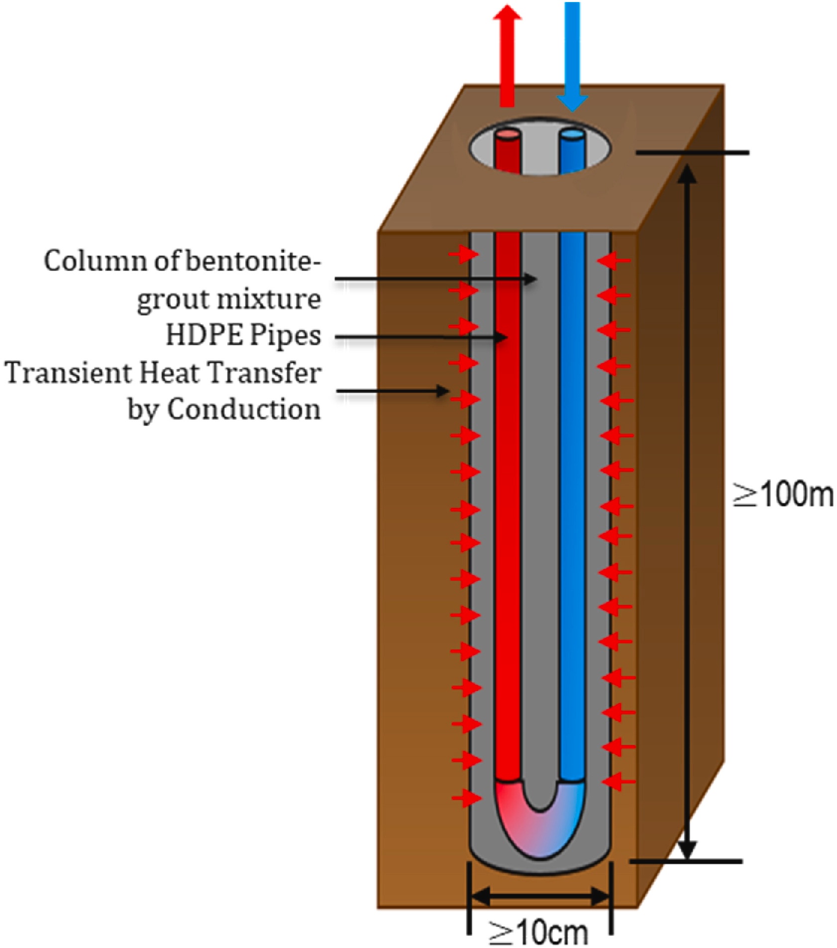
Figure 1. A vertical borehole heat exchanger extracting heat and returning cool fluid to the ground.
In Toronto, where Deacon works, all new buildings must be built in accordance with the Toronto Green Standard (Ref. 2), an initiative to reduce carbon emissions. The standard also has requirements for retrofitting. These requirements pose a challenge to engineers since they have to find a way to satisfy the heating and cooling needs of existing buildings that have very limited ground surface space. “By inclining the boreholes, spacing between adjacent boreholes at the surface can be reduced by up to 90%,” Deacon explains in his paper. A depiction of such borehole spacing can be seen in Figure 2.
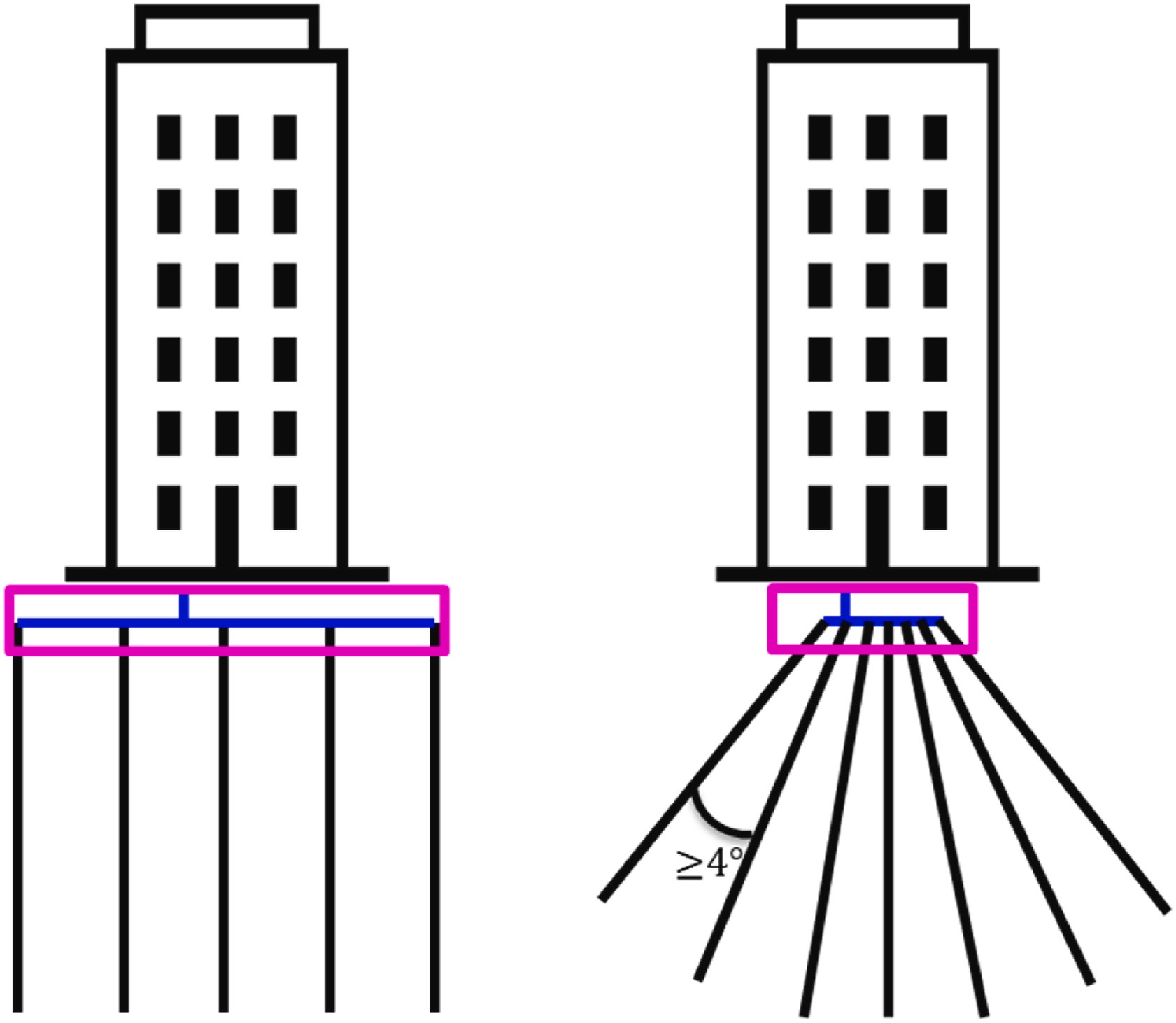
Figure 2. Angled boreholes greatly reduce the amount of ground surface area needed.
There is a lack of angled BHE modeling in the industry since most literature is based on vertical BHEs, which have resulted in assumptions of the heat transfer physics of angled BHEs. Deacon used the COMSOL Multiphysics® software to build 3D models of angled BHEs and compare their performance over time to vertical BHE models.
Collaboration and Testing Capabilities
Deacon built upon a BHE model developed by Tolga Ozudogru (Ref. 3) in COMSOL Multiphysics®. The model represented the fluid flow within the BHE as a one-dimensional pipe flow coupled with three-dimensional heat conduction in the surrounding solid material of the ground and rock. This pseudo-pipe method, as Ozudogru called it, saved significant computational effort compared to a complete 3D model of fluid flow in the pipe. The pseudo-pipe method couples the Heat Transfer in Pipes interface and the Heat Transfer in Solids interface in COMSOL Multiphysics®. It treats the flow and heat transfer through the pipes as transient and 1D, with coupling to the boundary of the 3D solid domain, which is where the 3D transient heat conduction equation is solved. The 3D numerical model of the heat conduction in the surrounding solid material uses the finite element method (FEM). Deacon used the Heat Transfer Module, an add-on product to the software, to develop a working composite model that couples computational fluid dynamics (CFD) and 3D transient heat conduction. This composite model captures the multiphysics effects occurring in angled BHEs.
The simulations were validated with experimental data collected by Richard Beier (Ref. 4) in an experiment featuring a rectangular sandbox with a U-tube heat exchanger in the center. Fluid was circulated through the pipe and heated between circuits. Thermistors were placed throughout the surrounding sand and measured the transient temperatures at various radial points. The inlet (supply) mass flow rate and temperature were then used as conditions for the numerical model. The results showed that the COMSOL Multiphysics® predictions of the fluid outlet (return) temperature and sand temperature at a range of radial locations were in good agreement with the experimental results.
An interrupted test was performed to simulate a 2-hour power outage. A heat flux was applied to the fluid to simulate what would happen in a power outage, while the initial conditions and boundary conditions for the soil domain remained the same as in an uninterrupted test the team performed, except for the inlet fluid temperature and flow rate. COMSOL Multiphysics® accurately predicted the temperature rise after restarting the circulation pumps and heaters after 2 hours without power, validating the solution of the transient heat conduction equation used in the experimental data (Figure 3). These studies gave Deacon confidence that COMSOL Multiphysics® can accurately model the heat transfer physics of a BHE.
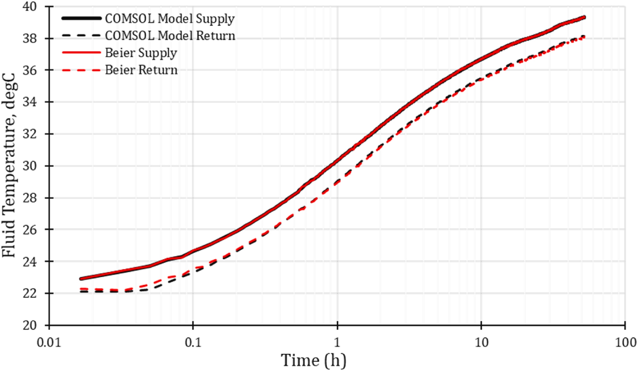
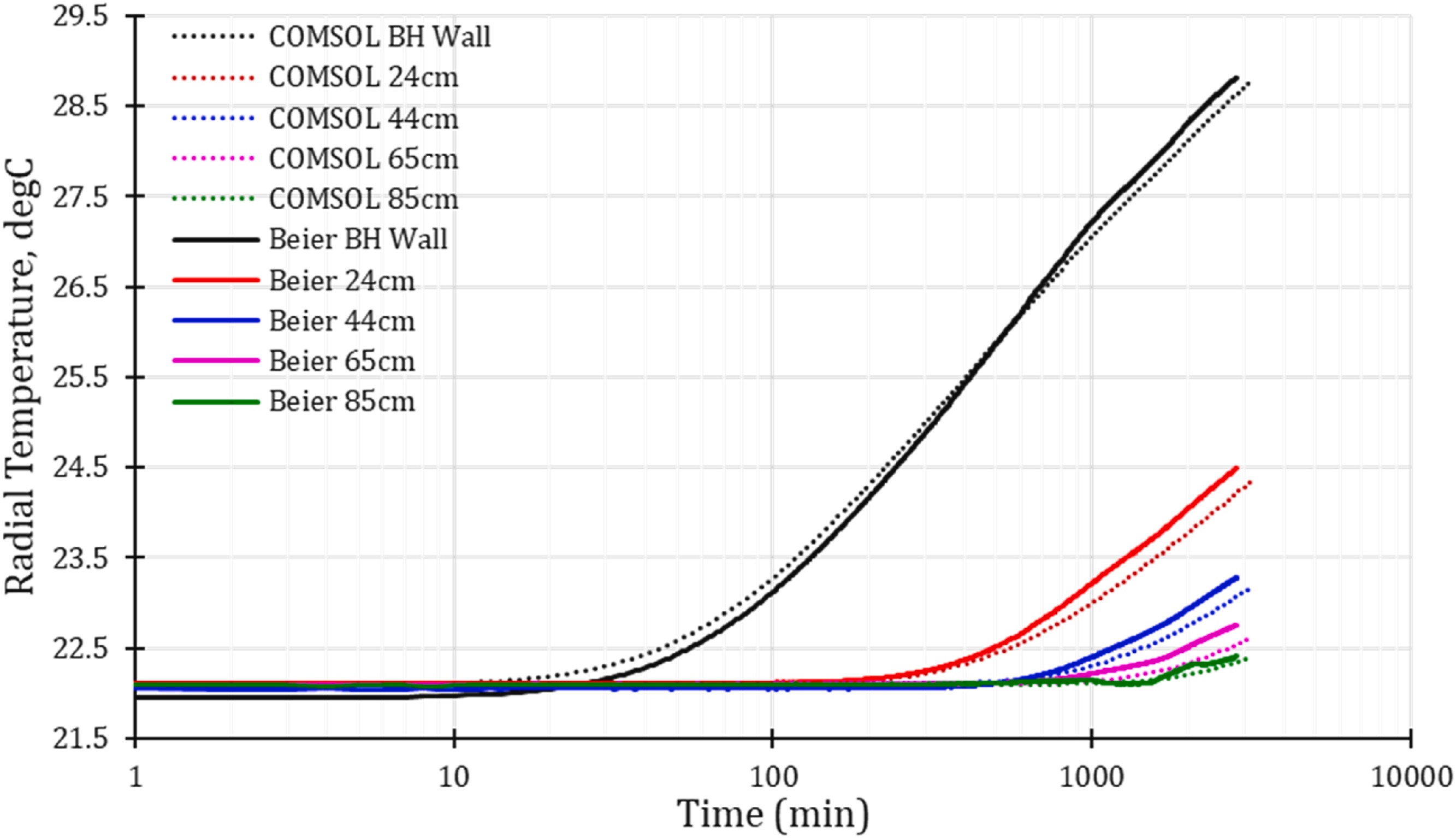
Figure 3. Left: The fluid temperature at the inlet (supply) and outlet (return) are in close agreement between the experimental data and the COMSOL Multiphysics simulation. Right: The temperature measurements at five radial locations from the experimental data compared to the COMSOL Multiphysics predictions.
Angled vs. Vertical BHE Performance
The study then analyzed the thermal response of three different BHE configurations (Figure 4) subjected to a constant heat injection rate. This study compares the thermal performance of:
- A single vertical BHE (1V)
- 2 parallel vertical BHEs positioned 5 meters apart (2V)
- A configuration with 1 vertical BHE and 1 angled BHE spaced 2.75 meters apart at the surface, with the angled BHE dipping 3 degrees from the vertical axis (1A1V)
The heat rate applied at the inlet was 20 kW, based on a typical rate used in industry thermal response tests. The total operation time simulated in the study was 8760 hours, or 1 year. The properties of the ground are representative of ground measurements in Southern Ontario. The operating conditions of the mass flow and heat rates at the inlet, the initial temperature bulk specific heat capacity of fluid, and the operation times were constant throughout the study, isolating thermal conductivity for analysis.
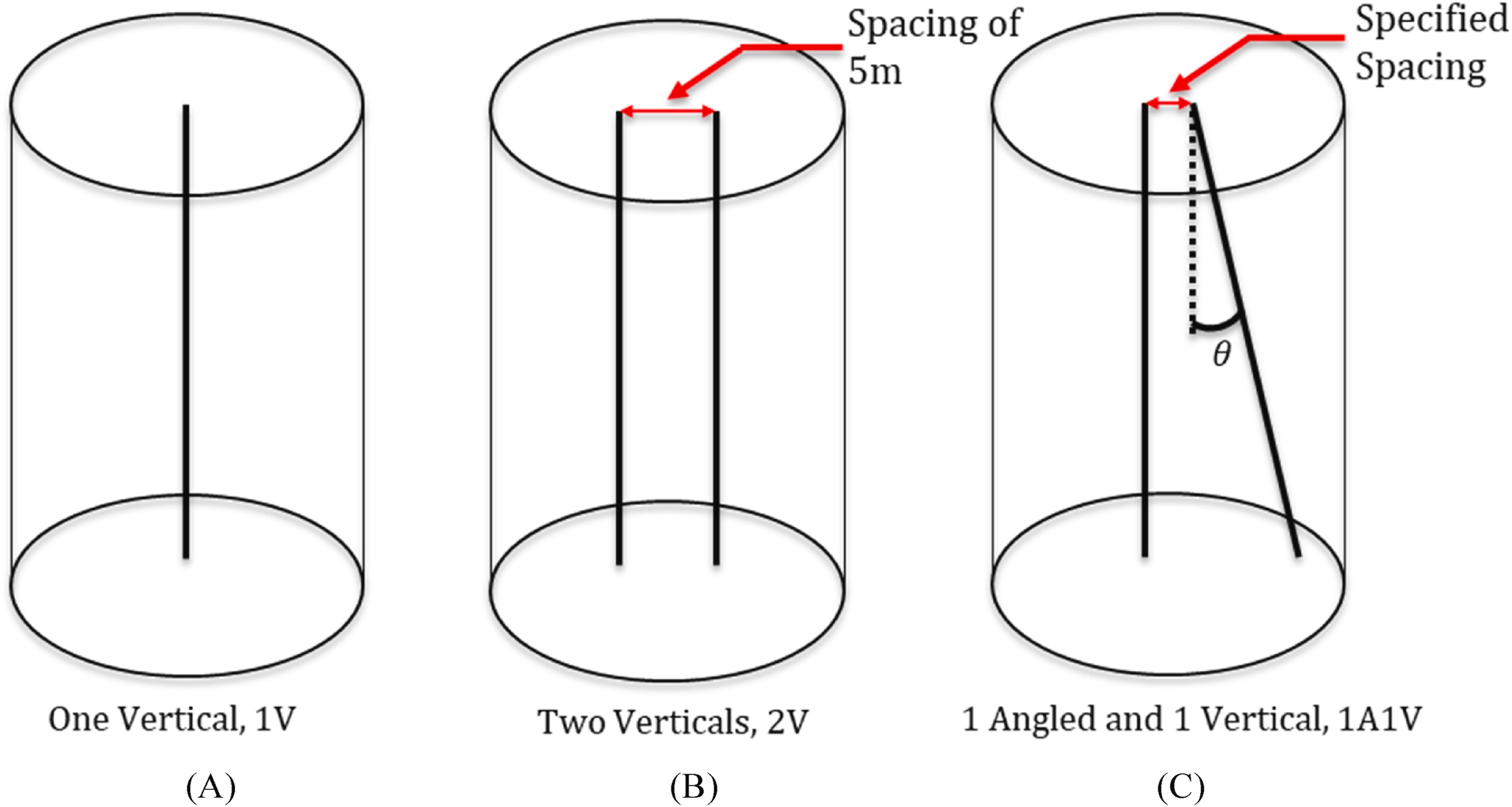
Figure 4. Visualization of three configurations of borehole heat exchangers to analyze thermal response.
The heat transfer in the 1V is considered optimal, thus, performance of the two other configurations is evaluated by comparing their fluid temperature with the 1V configuration. A temperature difference of 0 K represents optimal performance. Thermal interaction was expected to begin earlier in the 1A1V than the 2V due to the limited ground surface space. The thermal interaction manifests as an increase in the fluid temperature difference (relative to the 1V configuration). However, once thermal interaction begins in the 2V, it’s expected that the 1A1V will become more efficient over time.
Between operating hours 0–100, both configurations demonstrate a thermal performance akin to the 1V, or the optimal standard (maximum heat transfer). After the initial period of 100 hours, the fluid temperature for the 1A1V configuration increases up to 0.02°C greater than the 1V configuration. The greatest temperature difference peaks at approximately 690 hours and then decreases until 1053 hours, where the temperature profiles intersect each other (Figure 5).
When the two curves intersect, the temperature profile of the 1V rapidly diverges from the 1A1V due to thermal interaction along the full depth of the BHEs in the 2V configuration. The 1A1V configuration has reduced thermal interaction along its depths, resulting in a fluid temperature difference of approximately 1.4°C lower than the 2V at the end. The convergence point represents the transition from a minor adverse effect to a minor benefit in the performance of the 1A1V. The plot demonstrates that over longer periods of time, the 1A1V configuration exhibits better heat transfer than the 2V configuration.
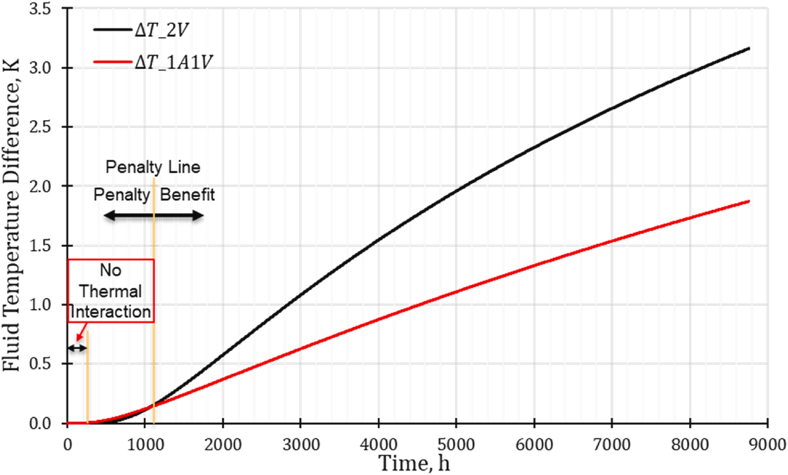
Figure 5. Fluid temperature differences between the 3 configurations under a constant heat injection rate.
Measuring Performance in Larger Systems
Most buildings larger than a single-family home require multiple BHEs. The quantity of BHEs needed is designed considering many factors, one being energy required to heat or cool the building on the coldest or hottest day of the year. Deacon used 4 BHEs to model the impact of different numbers of BHEs, with the operating conditions remaining the same (each borehole receiving the same flow rate and inlet temperature, thus, simulating the heat transfer performance of the different configurations).
The risk of additional BHEs is that thermal interaction escalates when the heat sources are closer together. His study used 3 configurations (Figure 6):
- 4V = configuration with 4 vertical BHEs
- 3A1V-configuration 1 = 3 angled BHEs and 1 vertical BHE with significant BHE separation
- 3A1V-configuration 2 = 3 angled BHEs and 1 vertical BHE with minimal BHE separation
Both angled configurations require less than half a square meter of ground surface area, whereas the 4V configuration requires 25 square meters. 3A1V-configuration 2 would be best suited for retrofitting a building with a smaller ground surface area, while 3A1V-configuration 1 would likely be best suited for a new building in an area with more ground surface.

Figure 6. The geometries of the three configurations for the 4-borehole example.
First, the simulation results showed that the performance per borehole declines when there is more than 2 BHEs. Compared to 2, there is a decline in performance per borehole; a minimal fluid temperature difference would be optimal, but the fluid temperature difference after 10 years is greater than 1 K, whereas it was less than 1 K in the 2-BHEs configurations. The decline in performance is attributed to increased thermal interaction and each BHE having less access to the ground volume due to being more crowded.
Regarding the 4-BHEs configuration, simulation results show that, in a 1-year time period, the fluid temperature differences for the 2 angled BHE configurations (3A1V-configuration 1 and 3A1V-configuration 2) are less than in the vertical BHE configuration (4V), proving that the angled configurations still exhibit better heat transfer performance. Of the 2 angled BHE configurations, configuration 1 results in significantly lower fluid temperatures throughout the year, demonstrating better performance due to the increased separation. In configuration 1, the fluid temperature difference after 10 years is approximately 1 K, while in configuration 2 the difference is approximately 2 K. Deacon deduced that optimizing the layout of the angled configuration will lead to better overall system performance. These results underscore the conclusions that have continually been drawn throughout the simulations and studies.
Simulation has led Deacon to the conclusion that angled BHEs are generally best suited for retrofits, while vertical BHE systems are generally preferred for new construction. When heat is continuously injected, both the angled field and the vertical field perform similarly initially, but over time, the angled field shows a significant increase in performance due to increased ground volume in the deeper part of the field. The angled field also shows better performance of the vertical field for cooling over a simulated period of 10 years. From these results, it was determined that the angled fields are better suited for handling imbalanced energy loads as well as utilizing ground volume.
“If you follow a couple of general rules when it comes to where to place the boreholes and what angles to use, they actually perform very similar to the traditional systems,” Deacon said.
Electrifying heating and converting conventional systems to geothermal energy systems has historically been expensive and inaccessible, but modeling and simulation has helped change that. Using COMSOL Multiphysics® enables engineers to estimate how boreholes will perform decades into the future, hour by hour. Furthermore, modeling can offer confidence in designs and help reduce the risk of errors.
“Now that we have this modeling capability, we can appropriately size up a borehole field, lower costs, and make [designs] much more feasible,” said Deacon.
References
- D.L. Deacon and M.F. Lightstone, “Three-dimensional analysis of multiple inclined borehole heat exchangers,” Renewable Energy, vol. 237, part B, 2024.
- Toronto Green Standard for New Low-Rise Residential Development, City of Toronto, Canada, Jan. 2017; https://www.toronto.ca/wp-content/uploads/2017/11/91f2-City-Planning-Toronto-Green-Standard-2017_LowRise_Standard.pdf
- T. Y. Ozudogru et al., “3D numerical modeling of vertical geothermal heat exchangers,” Geothermics, vol. 51, 2014.
- R. Beier et al., “Reference data sets for vertical borehole ground heat exchanger models and thermal response test analysis,” Geothermics, vol. 40, issue 1, 2011.


Comments (0)