
Modeling phase change is important for many thermal processes, ranging from the food industry to the metal processing industry. The Heat Transfer Module offers a dedicated interface for modeling the characteristics of phase change. It uses the apparent heat capacity method, which we introduce here.
Example: Continuous Casting
Phase change is a transformation of material from one state of matter to another due to a change in temperature. Phase change leads to a sudden variation in the material properties and involves the release or absorption of latent heat. We can use the Heat Transfer Module to model this type of phase change. Let’s start with an example.
In the continuous casting process, liquid metal is poured into a cooled mold and starts to solidify. As the metal leaves the mold, the outside is solidified completely, while the inside is still liquid. To further cool down the metal, spray cooling is used. When the metal is completely solidified, it can be cut into billets. This is a stationary, time-invariant, process. The rate at which the metal enters and leaves the modeling domain does not vary with time, and neither does the location of the solidification front.
Here is an illustration of the continuous casting process:
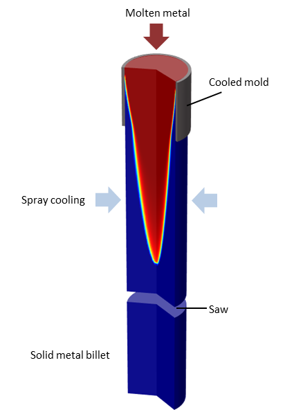
Sketch of a continuous casting process.
In order to optimize and improve this process, we can turn to simulation. With COMSOL software, we can predict the exact location of the phase interface.
Modeling Phase Change with the Apparent Heat Capacity Method
COMSOL Multiphysics and the Heat Transfer Module together offer a tailored interface for modeling phase change with the Apparent Heat Capacity method. The method gets its name from the fact that the latent heat is included as an additional term in the heat capacity. This method is the most suitable for phase transitions from solid to solid, liquid to solid, or solid to liquid. Up to five transitions in phase per material are supported.
When implementing a phase transition function, \alpha(T), a smooth transition between phases takes place, within an interval of \Delta T_{1\rightarrow2} around the phase change temperature, T_{pc, 1\rightarrow 2}. Within this interval, there is a “mushy zone” with mixed material properties. The smaller the interval, the sharper the transition.
The below figure shows the phase change function for the continuous casting model:
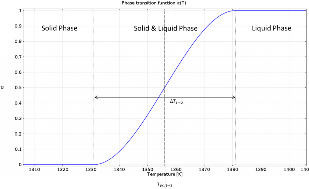
Phase transition function.
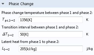
COMSOL Multiphysics settings for phase change. Keep in mind that phase 1 is below T_{pc, 1\rightarrow 2} and phase 2 is above.
The material properties for the solid and liquid phase are specified separately. These values are combined with the phase transition function so that there is a smooth transition from solid to liquid. The heat capacity of the material is expressed as C_p=C_{p,solid}\cdot(1-\alpha(T))+C_{p,liquid}\cdot\alpha(T), and similarly for the thermal conductivity and density. For a pure solid, \alpha(T)=0, and for a pure liquid, \alpha(T)=1. Within the transition interval, the material properties vary continuously.
The latent heat is included by an additional term in the heat capacity. Let us take a look at the derivative of the phase transition function:
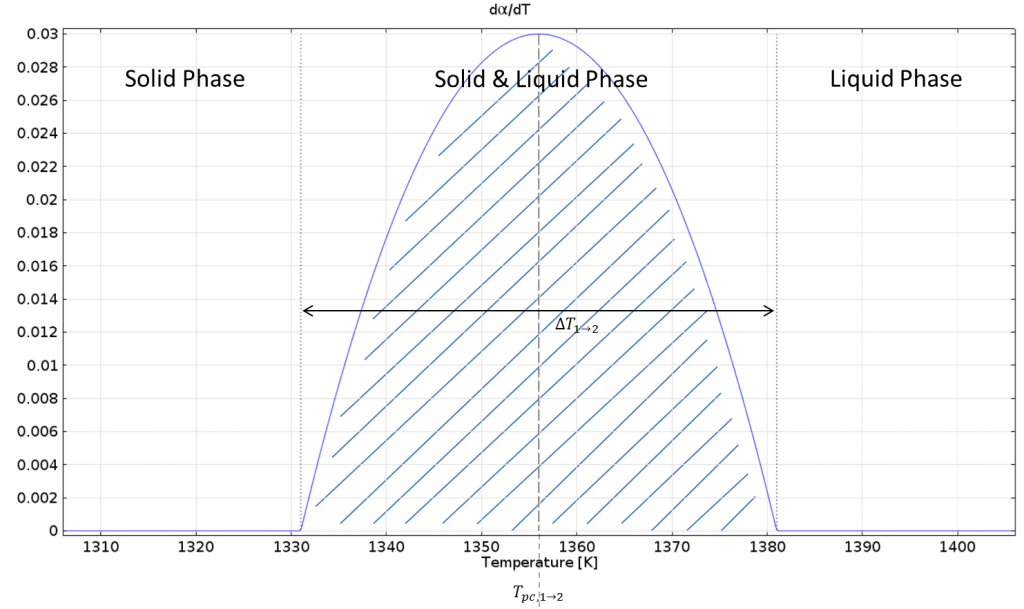
Derivative of the phase transition function.
Integrating this function over \Delta T_{1\rightarrow2} gives 1 and multiplying by the latent heat L_{1\rightarrow 2} gives the amount of latent heat that is released over \Delta T_{1\rightarrow2}.
Consider the stationary heat transfer equation with a convective term, of the form:
The Apparent Heat Capacity method uses the following expression for the heat capacity:
The advantage of this method is that the location of the phase interface does not need to be known ahead of time.
Application to the Continuous Casting Process
With the help of the Heat Transfer with Phase Change interface, the implementation is straightforward. Axial symmetry is assumed, and the model is reduced to a 2D domain. The casting velocity is constant and uniform over the modeling domain.
To get a sharp transition and thereby the exact location between the solid and liquid phase, we need a small transition interval, \Delta T_{1\rightarrow2}. Resolving such a small interval properly requires a fine mesh. However, we do not know the location of the solidification front in advance, so we first solve the model with a gradual transition interval, and then use adaptive mesh refinement to get better resolution of the solidification interface. The transition interval can then be made even smaller.
The results are compared below for two different transition intervals. As the transition interface is made smaller, the model better resolves the transition between liquid and solid. This information can be used to improve the continuous casting process, and this same approach can be used for similar applications involving phase change.
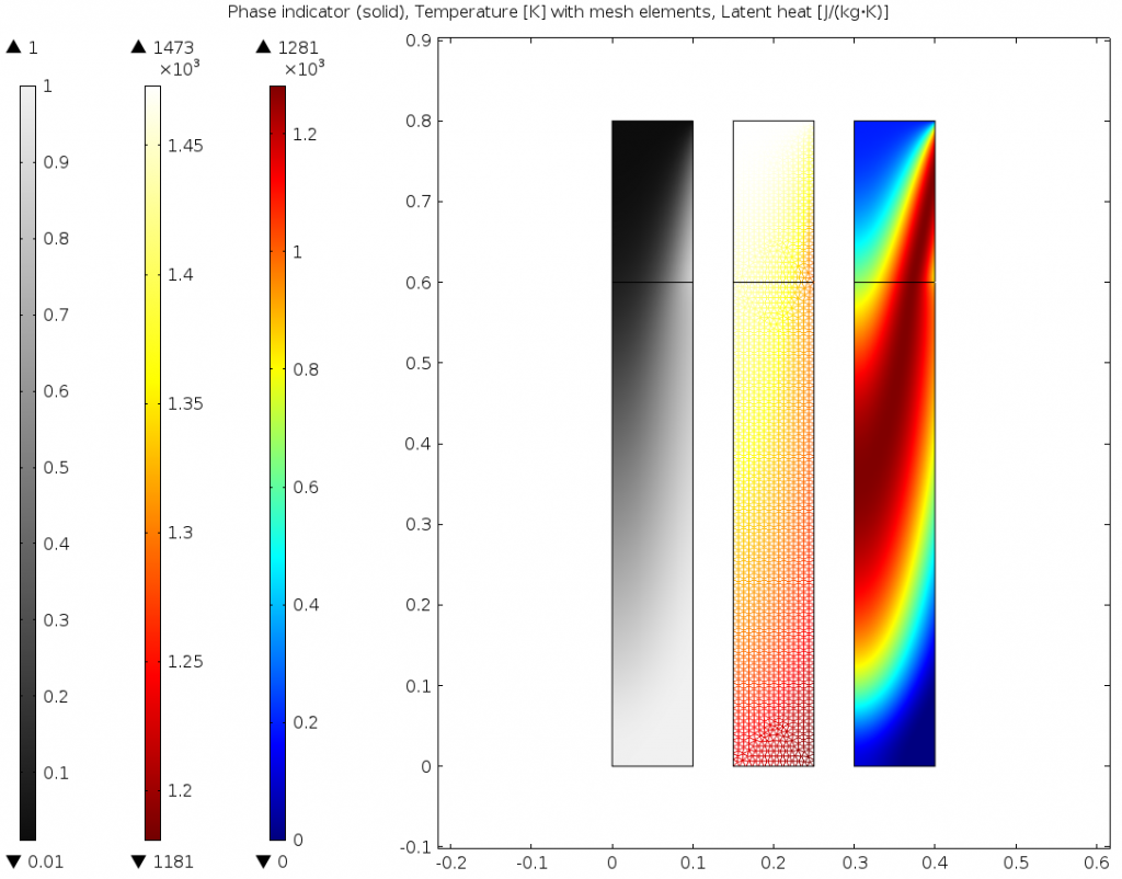
Phase, temperature, and latent heat for \Delta T_{1\rightarrow2}=300K on the uniform mesh.
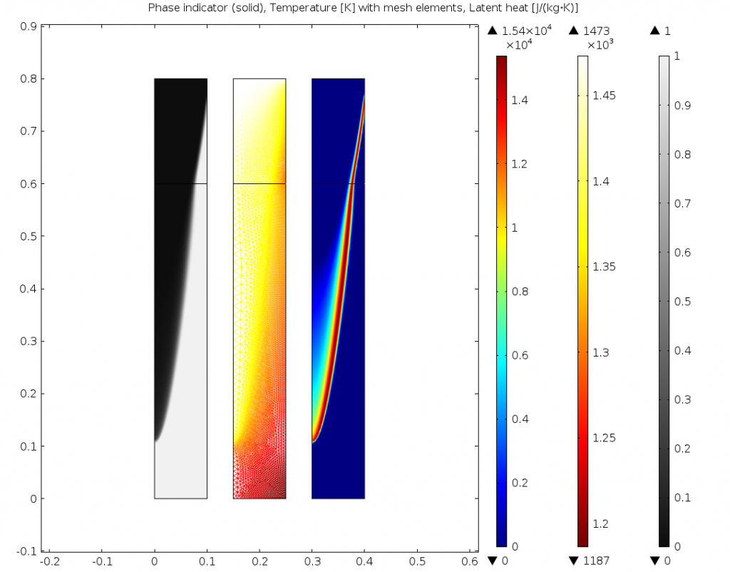
Phase, temperature, and latent heat for \Delta T_{1\rightarrow2}=25K on the adapted mesh.
Further Reading
- Download the model: Cooling and Solidification of Metal
- Read a user story: Optimizing the Continuous Casting Process with Simulation


Comments (30)
Denis Maus
August 29, 2014Hello,
looks interesting. Can one use this technique to model a “liquid-to-gaseous” phase-change, like in the case of heating water over the saturated temperature?
Kind regards,
Denis
Lun
March 27, 2016Hello,
That’s also my concern, but in 3D model.
Best regards,
Tran
Nancy Bannach
April 1, 2016 COMSOL EmployeeDear Denis, dear Tung,
for modeling liquid to gaseous phase change I recommend to have a look at another model from our application library: Evaporative Cooling of Water (https://www.comsol.de/model/evaporative-cooling-of-water-6192).
Liquid water evaporates as water vapor into a gaseous phase, whereas the gaseous phase is usually a mixture of (dry) air and water vapor.
Best regards,
Nancy
Anjana Thimmaiah
July 6, 2016Dear Nancy,
Does the Apparent Heat Capacity Method have a shortcoming in modelling liquid-gas phase change? Why is it not recommended for liquid-gas phase change modelling?
I used the model to simulate evaporation of a liquid film of water and used level-set to track the interface of the film. The simulation results concurred with most correlations.
Kind regards,
Anjana Thimmaiah.
Nancy Bannach
July 13, 2016 COMSOL EmployeeDear Anjana,
Basically, the Apparent Heat Capacity Method describes a sudden change in the material properties of one phase and accounts for the latent heat at this sudden change.
Usually, evaporation takes place between two materials (e.g. air and water) and not at a specific temperature, rather it depends on the saturation of the gas-phase (which depends on the temperature). If the gas phase is saturated with the liquid phase, no evaporation occurs.
To model this process (diffusion of the liquid phase into the gas phase, depending on the saturation) the apparent heat capacity method is not sufficient.
Of course, if the method works for you there is no need to change it. It may be suitable for some processes but in general, I would say, it is not.
Feel free to follow up on this discussion and/or contact us via support@comsol.com.
soy Noh
June 5, 2017Hello, I have a question.
Can it be possible?
Gas jet includes solid particles, and those particles can be sublimated into gas phase (by contacting hot plate).
Best regards,
Noh soy.
soy Noh
June 5, 2017Hello, I have a question.
Can it be possible?
Gas jet includes solid particles, and those particles can be sublimated into gas phase (by contacting hot plate)
Best regards,
Noh soy.
Nancy Bannach
June 22, 2017 COMSOL EmployeeDear Noh soy,
to answer your question properly we need more detailed information about your simulation. You could add a heat source at the boundary (hot plate) that is proportional to the incoming particles, but much more effects can be involved that you want to consider and the apporach shown here may be not sufficient in your case.
I recommend to contact our support team for discussion on this topic:
Online Support Center: https://www.comsol.com/support
Email: support@comsol.com
Best regards,
Nancy
Ying Zhao
October 5, 2018Hi Nancy,
Thanks for publishing this blog, it is very useful to understand apparent heat capacity method. But I found in COMSOL heat transfer with phase change interface, the build-in equations are not the same as you listed in the blog. Cp=(theta*rho,phase1*Cp,phase1+(1-theta)*rho,phase2*Cp,phase2)/rho + L*d(alpham)/dT
The theta is the phase1 fraction which =1 in solid and =0 in liquid (I think it is 1-alpha as in your blog?) But the alpham in those equation is defined as “mass fraction”. I don’t quite understand where this term comes from, could you explain more based on the equations used in COMSOL phase change interface?
Thanks,
Ying
Nancy Bannach
October 8, 2018 COMSOL EmployeeDear Ying,
Thank you for your feedback.
It is not sufficient to just use the phase indicator alpha, which is based solely on the temperature. For calculating the latent heat released during the phase transition, you also need to take into account the mass of each phase.
The “Theory for Heat Transfer with Phase Change” section in the Heat Transfer User’s Guide has outlined this very well. If you have further questions I recommend to contact our support team for a detailed discussion: https://www.comsol.com/support
Best regards,
Nancy
Anand Mohan
October 9, 2018Hi Nancy
Is it possible to simulate welding operation say in Laser Welding where there are two change in phase that is solid to liquid(heating cycle) and liquid to solid (cooling cycle). Is it possible to simulate this with the same concept and using two heat transfer with phase change(each one for a phsae change ) or we have to do something else?
With kind regards,
Anand Mohan
Sunku Prasad J
December 27, 2019Dear Nancy,
In the apparent heat capacity method, COMSOL is using the following equation for the density of the phase change material:
rho = theta*rho_phase1+(1-theta)*rho_phase2.
we know theta is a function of temperature.
If the density changes with the temperature, how the volume changes are accommodated?
How it is possible to change the density of the material without changing the volume (since the mass of the PCM is constant before and after melting)?
Kindly clarify.
Regards
Sunku prasad
Nancy Bannach
January 9, 2020 COMSOL EmployeeDear Sunku Prasad,
you are right, the volume changes are assumed to be small enough so that their influence on the simulation result is negligible. In many cases this assumption provides sufficiently accurate results. If you want to take volume changes into account, a coupling with a so-called ALE interface is required. This allows you to calculate the deformation due to density changes by deforming the mesh.
A good starting point to learn more about this can be found here:
https://www.comsol.com/blogs/model-deforming-objects-with-the-arbitrary-lagrangian-eulerian-method/
I hope this helps.
Best regards,
Nancy
Sobhan Azami
January 30, 2020Dear Nancy
In your opinion , what kind of physics and model should it be used to simulate the melting process of paraffin as a phase change material ?
If you have an example of this , please send me
I ” ll thank you for guidance
Nancy Bannach
January 31, 2020 COMSOL EmployeeDear Sobhan,
we have a model exemplifying the phase change of paraffin beside several other phenomena. The model treats the paraffin as a solid which is reasonable in this model.
https://www.comsol.com/model/packed-bed-latent-heat-storage-76181
Another model that may be interesting, but it uses water/ice is
https://www.comsol.com/model/frozen-inclusion-75381
Here also fluid flow of the water phase is include.
Both models use a heat transfer interface and the phase change feature for modeling phase change which is commonly used for solid/fluid phase changes.
If you want to discuss your problem in more detail, I recommend to contact our support team https://www.comsol.com/support.
I hope this helps.
Best regards,
Nancy
Sobhan Azami
February 6, 2020Dear Nancy
How to choose a black heat absorber plane on a box for Heat absorption from around for phase change in the box .
If you have an example of this , please send me
thank you very very much
Nancy Bannach
February 6, 2020 COMSOL EmployeeDear Sobhan,
If I understand you correctly, the boundary condition Surface-to-Ambient Radiation is the right choice. The emissivity of the surface and the ambient temperature are defined there, from which the value for the absorbed heat is calculated.
This boundary condition was also used in the continuous casting model discussed here.
I hope this answers your question.
Best regards,
Nancy
sepehr saber
March 26, 2020Hi Nancy, it seems that the model attached on your website is not the final model because in fluid and mixture properties 1 it reads “The value ‘ergun’ does not exist in combo box ‘nonDarcianModel’.”
Nancy Bannach
March 27, 2020 COMSOL EmployeeDear Sepehr,
I cannot reproduce this behavior with the current COMSOL version 5.5.0.359.
I recommend to contact our support team so that we can investigate what causes this error message.
Best regards,
Nancy
AYUSH PRATAP SINGH
May 29, 2020Dear Nancy,
Is there any example or model for solid-solid phase transition materials ?
Also if the specific heat changes with temperature how to take that into consideration while simulating PCM.
Regards,
Ayush
Nancy Bannach
June 3, 2020 COMSOL EmployeeDear Ayush,
I am not aware of any example for solid-solid phase transitions but it can be modeled with the same approach as discussed in this blog post. If the material properties like the specific heat capacity are defined as temperature dependent functions this is automatically taken into account. During phase change (within the transition interval) the material properties of both phases are mixed using the phase change function whereas the total heat capacity includes also the latent heat contribution (see the section “Modeling Phase Change with the Apparent Heat Capacity Method” in this blog post for details).
Are you specifically interested in metallurgical phase transformations have a look at our Metal Processing Module https://www.comsol.com/metal-processing-module.
Best regards,
Nancy
Alok Ray
November 21, 2020Hello Nancy.
Could you please tell for solid-liquid phase transition whether we’ve to define phase change fraction (alpha) as function of temperature or it’s already defined in COMSOL? Similarly properties of PCM during phase transition need to be defined or only values of solid and liquid PCM properties to be provided and COMSOL will automatically evaluate? Sometimes the properties of both phases are not known, then how to model at that time?
Regards
Alok Ray
Kidus GY
January 25, 2021Hello Nancy,
I was working on two PCM material mixed together and I was to simulate both using the same method you applied here. Is there a simulation example done on such mixed PCM material for comsol?
Thanks
Nancy Bannach
January 26, 2021 COMSOL EmployeeHi Kidus,
Every beginning is hard :-). There are numerous possibilities to plot the temperature over time, that’s why it is hard to give an answer for your specific application. I recommend to have a look at this model https://www.comsol.com/model/frozen-inclusion-75381 and how it is done there.
If you are new to COMSOL, I highly recommend to visit our learning center https://www.comsol.com/learning-center.
Especially for postprocessing we also have a handbook https://www.comsol.com/offers/Postprocessing-and-Visualization-Handbook-Part-1.
Finally, if you need further assistance with your particular model, please contact our support team https://www.comsol.com/support.
Best regards
Nancy
Lukas Borrmann
February 26, 2021Hello,
is it possible to describe the function a(T) manually? I have a transition curve (fraction liquid vs Temperature) for a specific alloy exported out of JMatPro and want to use it.
Kind Regards,
Lukas
Nancy Bannach
February 26, 2021 COMSOL EmployeeDear Lukas,
at the moment it is not possible to use a user-defined phase transition function, but we are aware that this option would be useful and plan to add it.
Please feel free to contact our support team to discuss your particular application. There are often other ways to accomplish what is asked for.
Best regards,
Nancy
Afaf Charraou
November 1, 2023I am seeking your expertise regarding a numerical model that I am currently developing in COMSOL Multiphysics. My objective is to model a phase change material layer integrated into a heated floor, and I would really appreciate any guidance on the physics to use as well as the associated equations.
Here is an overview of my project and the challenges I am encountering:
Geometry and Meshing:
I have already created the geometry of the multilayer heating element within COMSOL and generated a suitable mesh for the simulation.
Intended Physics:
I plan to include the following physics to model the heating phenomenon:
Heat transfer in the solid: To simulate the heat distribution throughout the floor layer.
Heat transfer in the fluid and laminar flow: My model involves fluid circulation within the heating layer when the phase change material transitions into the liquid phase.
Boundary and Initial Conditions:
I will define the appropriate boundaries and initial conditions for each physics module that I have selected.
Material Parameters:
I have defined the thermal and mechanical properties of the materials constituting the heating layer, such as thermal conductivity, thermal capacity, density, etc.
Questions:
1. How can I define the solid/liquid fraction?
2. How can I formulate the latent heat equation based on the fraction?
3. Between these physics modules, namely, Heat transfer in the solid and Heat transfer in the fluid, where can I define the phase change material condition?
Thank you in advance for your time and support. I am looking forward to your valuable input on this matter.
Best regards,
Nancy Bannach
November 6, 2023 COMSOL EmployeeDear Afaf,
I recommend you to take a look at the following example models from our Application Gallery. These models each use different approaches for modeling phase transitions:
1. https://www.comsol.com/model/cooling-and-solidification-of-metal-12701
2. https://www.comsol.com/model/tin-melting-front-6234
Have a look at the pdf file which also includes explanations and step by step instructions.
If you’re unable to make progress with these, it’s advisable to contact out support team (https://www.comsol.com/support) and ideally send your model along so that we can provide the best possible assistance.
Best regards,
Nancy
Feyzi Emrah Lasar
September 29, 2021I am trying to model an efervescant tablet that moves inside a spiral and releases gases. Unfortunately I tried everything and failed miserably every time. Any advice?
Sai Krishna
May 30, 2022please elaborate the term ‘alfa’.