
Batch reactors are used to manufacture a wide variety of products in the fine chemical, pharmaceutical, and food industries. In some cases, fine chemical processing may require more consistent operating conditions than batch reactors can offer, and continuous plate reactors may then provide better control of the process. Chemical modeling can help in the design of continuous plate reactors that are optimized for thermal control and product purity.
Batch Reactors Versus Continuous Reactors
The most common reactors in the chemical industry are tank reactors, which can be used as batch reactors or continuous reactors. Batch reactors process reactants one batch at a time, whereas continuous reactors carry reactants in a constant flow with continuous, steady-state production.
Batch reactors are used in a range of unit operations from mixing to crystallization, and are able to carry out a series of different reactions within the same container. Due to these abilities, they’re useful for testing new processes and manufacturing expensive products that are produced in relatively small volumes. For example, they are used in the fine chemicals industry, where the same reactor can be used for several processes (one at a time). Additionally, some chemicals aren’t suitable for continuous processes. Batch reactors are reliable options in, for example, fermentation processes and can even yield high conversion numbers for slow reactions, where you simply allow the process to run until completion.
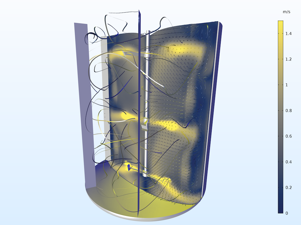
An image of a batch reactor mixer modeled in the COMSOL® software.
Continuous reactors are usually part of a continuous process that runs at steady state and may do so for many months without interruption. They are the most commonly used option for the production of bulk chemicals and petrochemicals, where the volumes are several orders of magnitude larger than in the fine chemical, pharmaceutical, and food industries.
Plate Reactors
One type of reactor is used as an alternative to the tank reactor in the fine chemical industry: the plate reactor. While expensive, there are times when a plate reactor is the best option for ensuring high-quality products. Since this type of reactor is used for relatively slow reactions, it works like a very long tubular reactor with a relatively large residence time.
Plate reactors are seldom used in bulk processes, since they give pressure losses that require large pumping power for large volumes. They are an alternative to tank reactors when temperature- or composition-sensitive products are manufactured, regardless of the process being batch or continuous. Plate reactors are a good option in fine chemical, pharmaceutical, and food processing applications in which quality is highly important, such as the pasteurization of milk, beer, or juice.
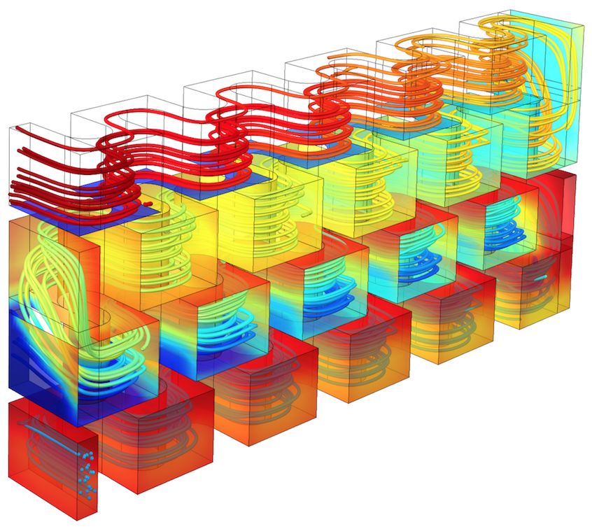
A model of flow through a unit cell in a typical plate reactor.
Using the Chemical Reaction Engineering Module, an add-on to the COMSOL Multiphysics® software, we can analyze the reacting flow in a continuous plate reactor design.
Modeling Chemical Production in a Plate Reactor with COMSOL Multiphysics®
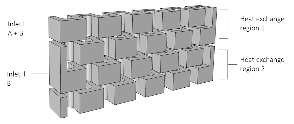
When modeling reactor plates and cooling/heating plates, we can treat the model setup as we would a heat exchanger model, in that the plates are stacked on top of one another. The 3D geometry of the model, below, shows the winding interior of the reactor plate. On the left side of the model, there are two inlet streams where reactants can enter the system:
- Inlet I, A + B, at the top of the reactor
- Inlet II, B, lower in the reactor
The heat exchange zones are also indicated, as they can affect the outer boundaries of the model.
In this example, there are two exothermic reactions that occur in an aqueous solution. The first reaction generates the desired product, D (A + B produces D). In the second reaction, the desired product reacts with B to produce the unwanted product, U (D + B produces U).
The design goal is to avoid generating an unwanted product in the plate reactor. Keeping in mind that the reactions are both exothermic and therefore prone to runaway temperatures, we need to find a way to dissipate the heat of the reaction so that the first reaction can proceed at a steady rate while inhibiting the second reaction. This outcome can be achieved via a cooling medium. The second half of the reactor exchanges heat with a cooling medium at a lower temperature than the first half.
Next, we account for the coupled momentum, energy, and mass transport within the plate reactor using the:
- Laminar Flow interface, which models the momentum transport (fluid flow) described by the Navier-Stokes equations at steady state
- Heat Transfer in Fluids interface, which models the energy balance
- Transport of Diluted Species interface, which models the mass transfer in the reactor domain, accounting for convection and diffusion
For more information on the boundary conditions for these three interfaces, refer to the model documentation in the Fine Chemical Production in a Plate Reactor tutorial.
Simulation Results
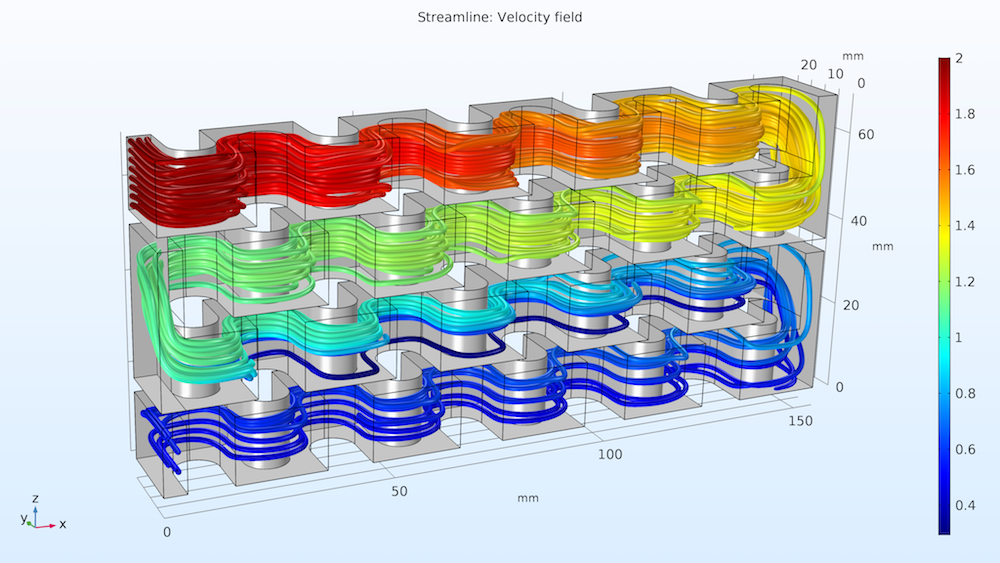
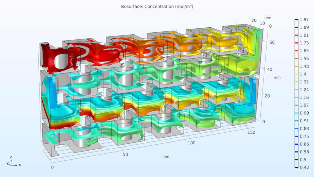
Let’s take a look at the streamlines of the fluid flow in the reactor plate. As shown below on the left, the concentration of reactant A is indicated by the color scale. We can see that the concentration is much higher at reactant A’s point of entry (Inlet I) at the top of the plate and decreases as it flows to the bottom. The second study’s results, below on the right, show the isosurfaces for the concentration of reactant B. Notice how the injection stream at Inlet II mixes with the main stream, causing reactant B’s distribution to be more uniform in the lower part of the reactor. Overall, we can see that the chemical reactions consume the reactant along the entire reactor volume.
Streamlines of fluid flow with the concentrations of reactant A indicated by color (left); concentration of reactant B (mol/m3) across the reactor volume (right).
Finally, we can examine the temperature distribution throughout the plates, represented below by horizontal and vertical cut planes. These results help us see how the heat expelled by the reactions quickly cools throughout the reactor because of the cooling medium we implemented in the model.
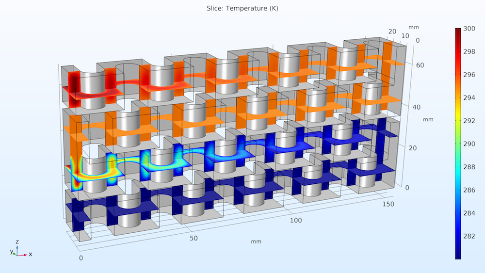
Temperature distribution in the reactor plate.
This example model can be used as a guide for setting up and solving the coupled flow, mass, and energy transport equations in a reactor system. With the chemical modeling capabilities of the COMSOL® software, you can further develop plate reactor designs to help predict fine chemical reactions and increase product quality.
Next Steps
Try modeling the plate reactor yourself: The button below takes you to the Application Gallery, where you can access the MPH-file and step-by-step modeling instructions.
Further Reading
Learn more about modeling chemical reactions and processes in the following blog posts:


Comments (1)
Yash Saraf
February 28, 2020A very useful & Informative blog. Got to know more about Fine chemical Production in a Plate Reactor
https://www.sarex.com/fine/