
Optical fibers that deliver midinfrared wavelengths are in high demand for a range of relative applications. As infrared transparent materials, semiconductors are useful for this purpose when combined with silica, helping to realize a new generation of midinfrared fiber optics. While important to performance, measuring the optical losses of such structures can be challenging experimentally because of time and costs. Simulation enables us to efficiently model this behavior for varying wavelengths and fiber geometries and identify strategies to reduce losses.
Semiconductors Help Advance the Design of Optical Fibers
Sensors, chemical imaging, and optoelectronics: These are just some of the applications in which midinfrared wavelengths are of significance. With their growing importance across various industries and technologies, the need for identifying optical fibers that can produce midinfrared light in a large wavelength range is increasing as well.
One approach is to fuse silica — a typical material for optical fibers — with infrared transparent semiconductors like germanium, zinc selenide, and silicon. To be more specific, silica makes up the cladding, or outer layer, of the optical fiber design and the selected semiconductor makes up its core. This combination provides opportunities for developing new types of midinfrared multimaterial optical fibers.
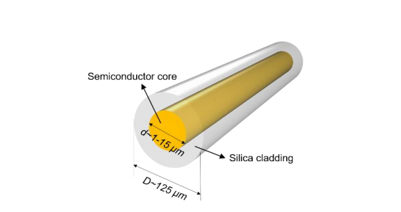
A multimaterial optical fiber design. Image by X. Ji, R. Page, and V. Gopalan and taken from their COMSOL Conference 2016 Boston paper.
In order for these optical fiber designs to be effective, an important step is to better understand their optical losses. While this can be time consuming and costly via experiments, simulation tools like the COMSOL Multiphysics® software provide a more efficient route for modeling this behavior and identifying means of optimization. Let’s look at an example from researchers at Pennsylvania State University and Pacific Lutheran University that involves the analysis and design of a germanium-based optical fiber.
Measuring Propagation Losses in a Germanium-Based Optical Fiber
For their analysis, the researchers used the RF Module, an add-on product to COMSOL Multiphysics. After defining their respective geometries, they applied refractive indices to both the core and cladding of the optical fiber at a particular wavelength. Along the outside of the cladding, the electric field is said to be zero. The plot below shows the electric field distribution for a characteristic HE11 mode that is confined and guided through a 6-μm core diameter made of germanium.
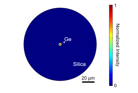
The electric field distribution of a characteristic HE11 mode within the core diameter. Image by X. Ji, R. Page, and V. Gopalan and taken from their COMSOL Conference 2016 Boston paper.
To identify the optimal fiber geometry and operative wavelength range, the research team simulated the mode’s propagation attenuation as a function of wavelength and core diameter. Between 2 and 4 μm, a window of low optical loss occurs. As the wavelength becomes longer, the loss begins to increase. This is due to the evanescent wave extending further into the cladding region and the increase in silica’s extinction coefficient at a longer wavelength. Note that the loss related to this effect is larger when the core diameter is smaller.


Left: The optical losses for the fibers. Right: The electric field distributions of the HE11 mode in the core diameter for varying wavelengths. Images by X. Ji, R. Page, and V. Gopalan and taken from their COMSOL Conference 2016 Boston paper.
For these longer wavelengths, one strategy for reducing optical loss and achieving a wider window of high transmission is to add another layer of material between the germanium and silica. This material needs to have smaller refractive indices than germanium and a smaller extinction coefficient than silica over a large wavelength range. Two good candidates for this are silicon and zinc selenide. In the plot below, we can see the characteristic HE11 mode confined and guided through each of these new fiber structures.
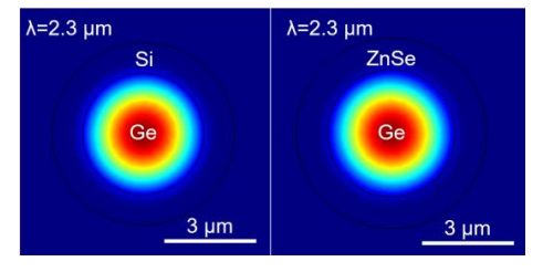
The electric field distribution of a characteristic HE11 mode within the core diameter when an interfacial layer is added. Image by X. Ji, R. Page, and V. Gopalan and taken from their COMSOL Conference 2016 Boston paper.
Once again, the researchers simulated the optical loss as a function of the wavelength for a 6-μm core diameter. As the results indicate, introducing the additional layer significantly reduces the optical propagation losses, particularly at longer wavelengths. What’s more: It does so without having to sacrifice the size of the core diameter.


Left: The optical losses for the fibers that include an added layer. Right: The electric field distributions of the HE11 mode in the core diameter at a wavelength of 10 μm. Images by X. Ji, R. Page, and V. Gopalan and taken from their COMSOL Conference 2016 Boston paper.
From the above results, it is clear that the reduction in optical loss is more pronounced in the zinc selenide case. This is because the refractive index between germanium and zinc selenide is greater than that between germanium and silicon, allowing light to be better confined. However, smaller refractive index differences often reduce the constraint of a small core diameter for single-mode guidance.
To account for this, the researchers calculated the single-mode guidance for each germanium-based core diameter configuration. The results show that the zinc selenide structure requires a smaller germanium core diameter to achieve single-mode guidance.
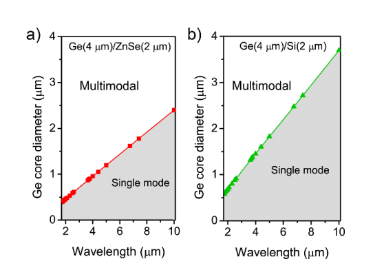
The germanium-based core diameter requirements for the zinc selenide (a) and silicon (b) structures. The gray areas represent conditions for single-mode guidance. Image by X. Ji, R. Page, and V. Gopalan and taken from their COMSOL Conference 2016 Boston paper.
Simulation Fosters the Design of a New Generation of Midinfrared Fiber Optics
With the flexibility of COMSOL Multiphysics, the research team was able to easily modify different parameters in their optical fiber design and analyze the impact on fiber performance. From there, they implemented further strategies to minimize optical losses and enable greater transmission. Their optimized fiber design has potential use in the medical field, specifically in endoscopes for spectroscopic imaging.
Resources for Modeling Optical Fibers in COMSOL Multiphysics®
- Read the full COMSOL Conference paper: “Design of Next Generation Mid-infrared Fiber Optics“
- Download related examples from our Application Gallery:


Comments (2)
sreelatha settipalli
November 20, 2018Thanks for the informative blog.
Ahmed Oudenani
January 25, 2023Thank you, Dr. Bridget Cunningham
Can you help to optimize the PCF photonic crystal fiber structure