
Human-powered vehicles like tricycles can provide a sustainable alternative to passenger vehicles and help riders avoid traffic in populated areas. Before a tricycle design is ready to roll, it needs to be optimized to meet safety requirements, which can prove difficult due to the complex structure of the tricycle. To efficiently pinpoint weak areas in a tricycle frame design, a research team used the Structural Mechanics Module with the COMSOL Multiphysics® software.
Taking a Closer Look at Tricycles
I tend to associate tricycles with children and picture them as small, brightly painted toys that are built more for enjoyment than practicality. However, tricycles are also a sustainable method of passenger transport and can even be used to transport bulk loads.
This application inspired the United Parcel Service (UPS) to use electric tricycles to deliver packages in Portland, Oregon, as well as other parts of the world. Although tricycles can’t carry as much as a typical UPS van, they are an alternative to emission-heavy vehicles and also help delivery drivers avoid traffic.
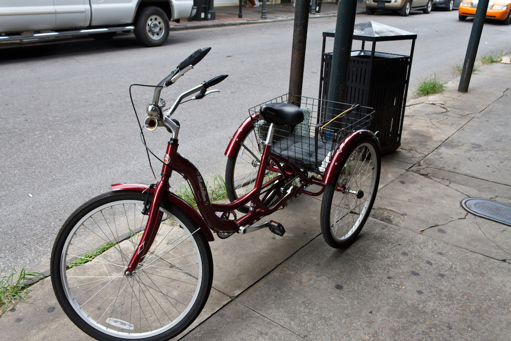
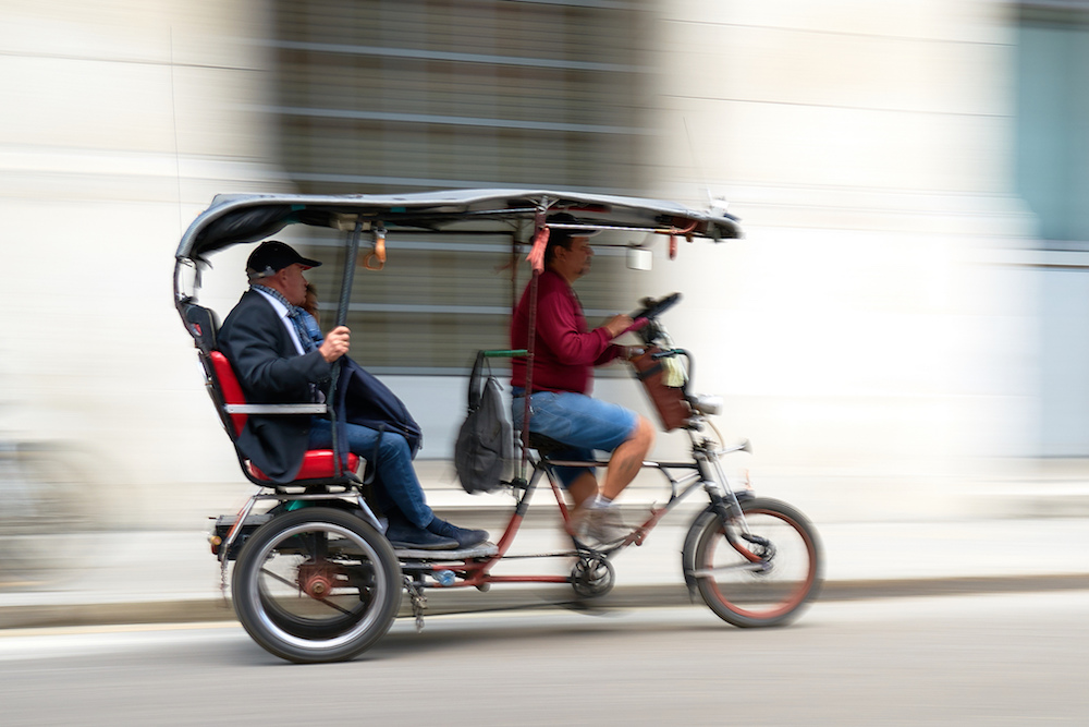
Tricycles can be used for many purposes, such as transporting loads and passengers. Left: Image by Gary J. Wood — Own work. Licensed under CC BY-SA 2.0, via Flickr Creative Commons. Right: Image by Pedro Szekely — Own work. Licensed under CC BY-SA 2.0, via Flickr Creative Commons.
We can use simulation to study a tricycle’s structure and ensure that it meets safety requirements. As an example, let’s consider a MUR-A tricycle developed by researchers from the Costa Rica Institute of Technology. To detect and address possible weak points in the tricycle’s design, the team used the Structural Mechanics Module with COMSOL Multiphysics to evaluate the mechanical performance of its frame. This enabled the team to find faults in the early stages, thereby optimizing the tricycle’s design before creating a physical prototype.
Studying an Aluminum Tricycle Frame with Structural Mechanics Analysis
The research team’s model consists of an aluminum 6063-T83 tricycle frame that uses steel 4130 for the handlebars and bottom bracket. As we can see in the following schematic, the frame is made of standard tricycle parts and includes a rear passenger or load zone. The team imported the 3D tricycle frame design into COMSOL Multiphysics using the CAD Import Module.


Tricycle components (left) and mesh (right). Images by A. Rodríguez, B. Chiné, and J. A. Ramírez and taken from their COMSOL Conference 2016 Munich paper.
To analyze their design, the researchers applied loads to different areas of the geometry. While the frame is the only tricycle part modeled, the team used other parts — seat tube, fork, handlebar, etc. — to define the loading conditions. These conditions include:
- Impact force (light blue)
- Pushing and pulling on the handlebars (gray and orange)
- Pedaling force on the bottom bracket (yellow)
- Driver’s weight (blue)
- Passenger’s weight (green)
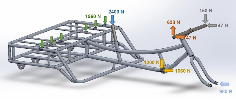
The locations of the various loads applied to the geometry. Image by A. Rodríguez, B. Chiné, and J. A. Ramírez and taken from their COMSOL Conference 2016 Munich poster.
Using different combinations of the loading conditions, the team studied three distinct loading cases, shown in the table below. You can easily combine several sets of loads in COMSOL Multiphysics by using load groups and load case superpositions.
| Impact Force | Pushing and Pulling on the Handlebars | Pedaling Force on the Bottom Bracket | Driver’s Weight | Passenger’s Weight | |
|---|---|---|---|---|---|
| Acceleration | X | X | X | ||
| Steady Pedaling | X | X | |||
| Horizontal Impact | X | X |
In regards to the horizontal impact case, it represents a sudden impact against a wall and assumes that the driver is removed from their seat while the passenger remains on the tricycle. As such, this case only accounts for the impact force and the passenger’s weight.
For each of these loading cases, the team performed a simple evaluation of the model’s stress and deformation distributions, enabling them to identify design issues and develop a safer tricycle.
Checking for Critical Areas in a Tricycle Frame Design
Overall, the simulation results show that in every loading case, there are regions in the tricycle frame design that are susceptible to stresses above the tensile yield strength of 214 MPa and the fatigue limit of 69 MPa. The researchers did not analyze the horizontal impact case for fatigue strength, as this is not (hopefully) a continuous condition.
In the steady-state pedaling case, there are critical areas that exceed the material’s elastic limit, located where the seat and horizontal tubes meet. This is expected, as the rider’s weight causes compression in these areas. Other areas of concern are the places where the horizontal tube and down tube intersect with the cage.


The steady pedaling case. Red indicates the areas where the von Mises stresses are greater than the material’s elastic limit (left) as well as the areas that are stressed more than the material’s fatigue limit resistance (right). Images by A. Rodríguez, B. Chiné, and J. A. Ramírez and taken from their COMSOL Conference 2016 Munich paper.
As for the fatigue evaluation in this scenario, one area (extending from where the seat and down tube meet to the front of the frame) fails when exposed to a static load behind the seat tube. This static load is a potential source of fatigue failure, since it is sometimes active and sometimes not.
There are similar weak areas where the horizontal and down tubes intersect with the cage. The results indicate that additional critical areas are located at the unions of the reinforcement tube, the cage area before the rear axle, and the intersection of the head and down tube.
The acceleration loading case has the same fatigue areas as the steady-state case, but spread over a smaller area. However, there is one difference. The intersection of the head and down tubes has a critical area that is slightly larger than the steady pedaling case, extending to the bottom of the down tube.
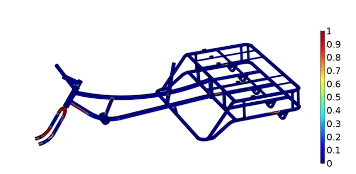
The acceleration case. Red indicates the areas that are stressed more than the material’s fatigue limit resistance. Image by A. Rodríguez, B. Chiné, and J. A. Ramírez and taken from their COMSOL Conference 2016 Munich paper.
The team then investigated the horizontal impact case. When comparing their numerical results with the material’s elastic limits, they saw that although the frame can withstand these loads, there are critical areas in the cage.
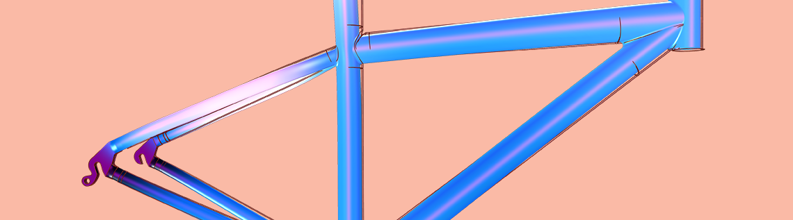
Examining the frame’s fork region for this loading case, the team saw that it behaves similarly to the frame as a whole. The results show that when the fork is exposed to the impact force, there are only a few deformation areas, shown in the following image. Despite this, the fork region may need to be redesigned, since it does not hold up under a fatigue analysis.
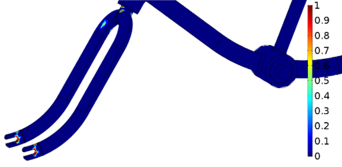
The fork region for the horizontal impact case. Red indicates the areas where the von Mises stresses are greater than the material’s elastic limit. Image by A. Rodríguez, B. Chiné, and J. A. Ramírez and taken from their COMSOL Conference 2016 Munich paper.
Next Steps for Studying a Tricycle Frame’s Mechanical Performance
Through their work, the researchers gathered helpful insight into the mechanical performance of their tricycle frame design. For instance, the simple fatigue analyses show that while most of the frame withstands static loads, it is compromised when it comes to long-term durability. As such, the tricycle frame needs to be strengthened.
According to existing research, one way to improve this design is to combat the tricycle frame’s low fatigue life by changing the material from aluminum 6063, with a fatigue limit of 69 MPa, to aluminum 6061-T6, which has a higher fatigue limit of 96 MPa.
While the simple analyses discussed today are a good starting point for improving the tricycle frame design, further studies (such as more fatigue and impact simulations) are required. Through this, the researchers can fine-tune their tricycle frame design, ensuring the safety of riders and passengers.
Further Reading
- Take a look at the researchers’ full paper: “Finite Element Modeling of an Aluminum Tricycle Frame“
- Browse the structural mechanics category on the COMSOL Blog


Comments (0)