

When you lose power at home, you may use a shaker flashlight to navigate about your house. This type of flashlight relies on voltage produced by electromagnetic induction in order to be powered. How much voltage can one of these flashlights produce, do you think? Here, we find out through computation, using the AC/DC Module.
Electromagnetic Induction
One way electromagnetic induction arises is when a stationary conductor is exposed to a time-varying magnetic field. The other way is by moving a conductor in a stationary magnetic field. In both cases, an induced voltage will develop across a conductor. Examples of the phenomenon are endless and many occur in everyday life; electrical generators, magnetic pickups on electrical guitars, and induction stoves are just a few applications where you can witness induction.
Each type of application involves numerous additional factors that contribute to the amount of voltage that can be produced in a specific device. The Voltage Induced in a Coil by a Moving Magnet model serves as a prime example of how you can determine the amount of voltage produced across a conductor through means of electromagnetic induction.
Shaker Flashlight
In the example model, electromagnetic induction produces voltage to charge a battery of a shaker flashlight (also referred to as a Faraday or linear induction flashlight).
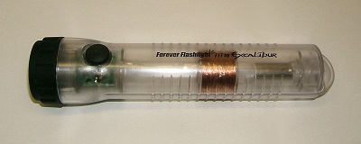
Linear induction flashlight.
In order to produce voltage in this type of flashlight, you shake it back and forth length-wise. The shaking leads to the oscillation of a powerful permanent magnet within (typically a rare-earth magnet). The magnet oscillates up and down through a multi-turn coil, causing the magnetic flux to change. This action is similar to a linear electrical generator and produces voltages on the coil’s walls. In turn, these create an electric current that powers the flashlight’s battery.
In our example, a magnet of strength 1.2 T is displaced sinusoidally at 4 Hz with a 30-millimeter peak displacement inside an 800-turn coil.
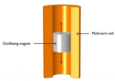
Oscillating magnet in a multi-turn coil.
Computing the Voltage
In order to solve for the voltage, you must take the integral of the magnetic fields over domains of the flashlight. The AC/DC Module contains a series of interfaces and functionality that allow you to do so based on the domain boundaries involved, among other factors.
This is a two-step process. First, we must perform a stationary analysis of the magnetic fields. Doing so allows us to provide the appropriate initial conditions for performing the second step: a transient analysis of the magnetic fields. If we solve our model, we will get the following plot, depicting the induced voltage in the coil:
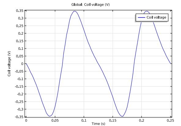
Induced voltage for the coil’s open circuit configuration.
Modeling the Motion
Along with computing the voltage, this example also models the motion of the magnet. Here, the displacement of the magnet is significant. This model uses a moving and sliding mesh functionality to define the displacement of the magnet and the surrounding air domains.
Motion of the magnet.
It is best to define the Moving Mesh physics in the magnet and the air domains because neither the coil nor air domains surrounding it need to deform.
Concluding Thoughts
A number of external factors can influence the amount of voltage induced in this particular scenario, including the components of the flashlight as well as how fast the flashlight is shaken. Considering that the amount of electricity produced depends on how fast the flashlight is shaken (changing the magnetic flux), how do you suppose the amount of voltage would change if we shook a flashlight containing a 1,000-turn coil twice as fast?
Model Download
- You can build the model by downloading it from the Model Gallery: Voltage Induced in a Coil by a Moving Magnet

Comments (3)
Ehsan Mohseni
December 9, 2014Hi
I tried the same procedure used in this example to create a moving mesh for a 3D eddy current coil scanning over a conductor plate, (I fixed the plate and applied the deformation to eddy current coil and its surrounding air domain), but I couldnt get correct results. In the shaker flash light example, boundary condition for the interface of moving mesh domain and stationary mesh domain is defined by continuity pair which can not be used for stratified 3D eddy current problem and also I couldnt find any other proper boundary condition to apply to my model. It would be really helpful if you could enlighten me about this procedure in 3D.
Regards,
Adrian Rendon-Hernandez
October 14, 2020Hello Ehsan,
By chance did you receive any further information?
Thanks
Adrian
Adrian Rendon-Hernandez
October 14, 2020Hello,
It’s been a longtime I’ve been trying a similar procedure on a moving mesh for a 3D model. Any of you have more information about it?
Thanks
Adrian