
In any form of treatment, it is always desirable to minimize the level of discomfort that the treatment process causes patients, while ensuring overall safety and effectiveness. For diabetes patients, insulin injections remain an important form of treatment, but the process itself can be painful. With the help of multiphysics simulation, a team of researchers from the University of Ontario Institute of Technology sought to develop a MEMS-based micropump that could administer insulin injections in a safe and painless way.
Treating Diabetes with Insulin Injections
The food that we consume on a day-to-day basis, particularly carbohydrates, is a powerful source of energy for the human body. For the body to utilize energy from carbohydrates and store glucose for later use, it is crucial that its cells properly absorb the sugar. The key to this process is insulin, a hormone the body signals to the pancreas cells to release into the bloodstream, allowing sugars to enter the cells and be used for energy.
But what happens when the body fails to produce enough insulin or if it doesn’t work in the way that it should? In this case, the glucose fails to be absorbed by the cells and will instead remain in the bloodstream, resulting in rather high blood glucose levels. Referred to as diabetes, this metabolic disease relates to cases where the body produces little or no insulin (Type 1) or does not properly process blood sugar or glucose (Type 2). Note that in the latter type, a lack of insulin can develop as the disease progresses.

A device for injecting insulin. Image by Sarah G. Licensed under CC BY 2.0, via Flickr Creative Commons.
In both Type 1 and Type 2 diabetes, insulin injections serve as a viable treatment option. These injections, however, can cause pain when applied by a heavy single-needle mechanical pump. To minimize patients’ discomfort, researchers have investigated the potential of using a microneedle-based MEMS drug delivery device to administer insulin dosages. Not only would the stackable structure be minimal in size and easy to apply to the skin, but it would also provide a safer and less painful approach to applying injections.
Here’s a look at how a research team from the University of Ontario Institute of Technology used simulation to evaluate such a device…
Designing and Analyzing an Insulin Micropump: A True Multiphysics Problem
Let’s begin with the design of the micropump model. The researchers developed a MEMS-based insulin micropump, placing a piezoelectric actuator on top of a diaphragm membrane comprised of silicone, with a viscous Newtonian fluid flowing through it. Note that the design itself is based on the minimum dosage requirement for diabetes patients — this typically ranges from 0.01 to 0.015 units per kg per hour.
Vibrations from the actuator create a positive/negative volume in the main chamber of the pump, which then pulls the fluid from the inlet gate and pushes it toward the outlet gate. Two flapper check valves control the direction of the fluid from the inlet to the outlet leading to the microneedle array, with a distributor connecting the outlet gate to the microneedle substrate. The established discharge pressure then pushes the fluid out of the microneedles to the skin’s outer layer.
The following set of images show the dimensions and cross section of the micropump as well as a more detailed layout of the model setup, respectively.
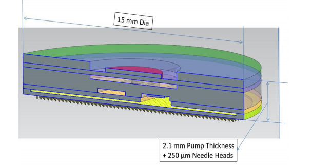
The MEMS-based piezoelectric micropump design. Image by F. Meshkinfam and G. Rizvi and taken from their COMSOL Conference 2015 Boston paper.
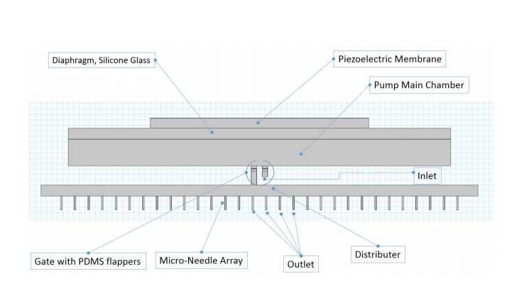
A 2D layout of the micropump model setup. Image by F. Meshkinfam and G. Rizvi and taken from their COMSOL Conference 2015 Boston paper.
To accurately study the performance of the micropump, the researchers utilized three different physics interfaces in COMSOL Multiphysics: the Solid Mechanics, Piezoelectric Devices, and Fluid-Structure Interaction (FSI) interfaces. The fluid flow that occurs from the inlet to the outlet via the action of the flapper check valve is described by the Navier-Stokes equations. Upon a wave signal exciting the piezoelectric actuator, the diaphragm disk and piezoelectric actuator move together, with an FSI moving mesh presenting the deformed solid boundary to the fluid domain as a moving wall boundary condition. Within the solid wall of the pump, this moving mesh follows the structural deformation. The FSI interface also accounts for the fluid force acting on the solid boundary, making the coupling between the fluid and solid domains fully bidirectional.
For their simulation analyses, the research team applied different input voltages and input exciting frequencies to the micropump design, studying various elements of the device’s behavior. The range of the voltages spanned from 10 to 110 V, while the exciting frequencies ranged from 1 to 3 Hz.
Let’s look at the results for an input voltage of 110 V and an input exciting frequency of 1 Hz. The plot on the left depicts the inflow and outflow rates, showing very little leakage for both. The plot on the right shows the established discharge and suction pressures at the inlet and outlet. At the inlet gate, a negative pressure denotes suction pressure, while a negative pressure at the outlet gate represents discharge pressure.


Left: Inflow and outflow rates. Right: Discharge and suction pressures. Images by F. Meshkinfam and G. Rizvi and taken from their COMSOL Conference 2015 Boston paper.
As part of their analyses, the researchers measured the stress and deflection of the flapper check valves as well as the velocity field of the fluid. You can see their results in the following set of plots.


Left: Von Mises stress in the flapper check valves and velocity field of the fluid. Right: Deflection of the flapper check valves. Images by F. Meshkinfam and G. Rizvi and taken from their COMSOL Conference 2015 Boston paper.
The studies shown here, as well as those conducted with alternative inputs, indicate that the micropump design performs properly from the minimum to maximum spectrum of pressure and flow rates. Such a configuration can therefore serve as a viable alternative for applying insulin injections, providing a safer and less painful method of treatment for diabetes patients. The researchers hope to use their simulation findings as a foundation for creating more durable and dynamic insulin micropump designs in the future.
Read More About Using COMSOL Multiphysics to Optimize Treatments
- Learn more about the research presented at the COMSOL Conference 2015 Boston: “Design and Simulation of a MEMS Based Piezoelectric Insulin Micro-Pump“
- Explore further applications of simulation for improving methods of treatment on the COMSOL Blog:


Comments (0)