
A fast charging time and long lifetime are desirable qualities for rechargeable batteries. However, a higher charge rate often results in a nonuniform current distribution in the active electrode material in the cell while charging or discharging (i.e., a nonuniform electrode utilization). This leads to localized aging and a shorter battery life. Designers can use the COMSOL Multiphysics® software to predict the electrode utilization in a battery for various charge rates.
Benefits of Large-Format Lithium-Ion Battery Pouch Cells
Lithium-ion (Li-ion) batteries have many benefits over other rechargeable batteries. They can go longer in between charges due to their high energy density, keep their charge longer than their counterparts thanks to their low self-discharge rate, and don’t require as much maintenance. Because of these qualities, they are especially good for scenarios requiring large-format batteries, including:
- Energy storage systems (e.g., for solar and grid power)
- Electric, hybrid, and plug-in cars
- Unmanned vehicles
- Light-rail trains
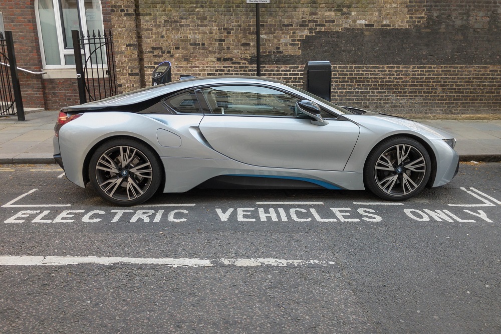
Large format Li-ion batteries are commonly used in electric vehicles. Image by Marco Verch. Licensed under CC BY 2.0, via Flickr Creative Commons.
Depending on the usage, rechargeable Li-ion battery cells can be packaged into cylindrical, prismatic, and pouch cells. While the cylindrical cell is the most common (having been developed nearly 100 years earlier than the others), prismatic and pouch cells are gaining popularity. This is mostly thanks to new technology lowering the manufacturing costs and weight for these cells, as well as their potential for having a higher capacity than cylindrical cells. As for pouches in particular, they are the thinnest and lightest of these rechargeable cell types as well as the best in terms of packaging efficiency.
For large-format lithium-ion battery packs, cells are connected together in series or in parallel, which is called a module. Modules can be similarly connected to form full battery packs. To improve large-format battery packs, it is useful to study a single electrochemical cell and make sure it has a uniform electrode utilization, as this type of analysis can help direct the design and optimization of large-format cells.
When it comes to designing pouch cells for large-format Li-ion batteries, two important but often contrasting considerations are the cell’s lifetime and charge rate. Rapid charge or discharge rates can significantly affect the local reaction rates inside the pouch cell and cause it to wear out quicker. The lifetime of large-format pouch cells is also heavily impacted by aspects like the cell geometry, material thickness, and current collector tab locations. These factors can all increase (or decrease) variations in the current, temperature, and state of charge (SOC) for the battery, making the electrode utilization less (or more) uniform.
To analyze the design of large-format Li-ion battery pouch cells, engineers can use COMSOL Multiphysics and the add-on Battery Design Module. With the COMSOL® software, they can study the electrode utilization for different design and operation parameters; e.g., various charge rates. Let’s take a look at one example…
Analyzing the Electrode Utilization in a Battery Design
This example demonstrates modeling a large-format Li-ion battery pouch cell in 3D. Here, the pouch cell is charged from 20% to 80% SOC, with lithium ions moving from the positive electrode to the negative electrode. The example, which consists of a foil-to-foil unit cell, includes a:
- Negative metal current collector foil and tab (where charging current is applied)
- Negative electrode (grounded)
- Separator
- Positive electrode
- Positive metal current collector foil and tab
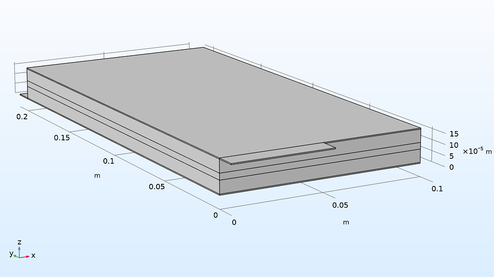
Model geometry of the Li-ion pouch cell battery, scaled by 100x in the z direction (see grid) to see the layers clearly.
As for defining the material properties, the material library available in the Battery & Fuel Cells Module contains common electrode and electrolyte materials, simplifying the model setup. Here, you can use lithium manganese oxide and graphite for the positive and negative electrodes, respectively. Then, lithium hexafluorophosphate (LiPF6 in 3:7 EC:EMC) is used for the liquid electrolyte, while aluminum and copper are the materials for the current collector.

Screenshot showing the materials for the electrode and electrolyte in the Li-ion pouch cell battery.
To define the problem, you can take advantage of the Lithium-Ion Battery interface, which can be used to analyze the current, SOC, and potential distribution in a Li-ion battery. With COMSOL Multiphysics, you can model various cell geometries and study the effects of the position and thickness of the current collector tab, thickness of the active electrode material, and porosity of the electrodes and separator. Additionally, you can model the physical and chemical processes inside the battery (such as the particle intercalation and reactions happening in the porous electrodes) by including an extra particle dimension, via the Porous Electrode node and Particle Intercalation subnode. This enables you to model up to “pseudo-4D” (x, y, z, and r), taking all length scales into account.
After defining the model, you can analyze how different charge rates affect the performance of the battery with a time-dependent study node. In this example, two different charge rates are solved for:
- 1C (also called a 1-hour charge)
- 4C (a 15-minute charge)
As mentioned above, the battery is only charged between 20 and 80%, so the total times are slightly shorter: 42 minutes for 1C and 10.5 minutes for 4C.
Examining the Simulation Results for the Large-Format Li-Ion Battery
First up in the results, you can examine the maximum and minimum initial electric potential for both the positive and negative electrodes before the battery starts to charge. This enables you to determine how much variation there is between the two tabs, as this can affect the uniformity of the electrode utilization. For the 1C charge, the variation is small: 3 mV for the positive electrode and 1 mV for the negative electrode. Therefore, the electrode utilization should be fairly uniform. However, the variation is more than double that for the 4C charge rate, with the electric potential being 10 mV in the positive electrode and 6 mV in the negative electrode.

Electric potential distribution in the positive and negative electrodes for the 1C charge.
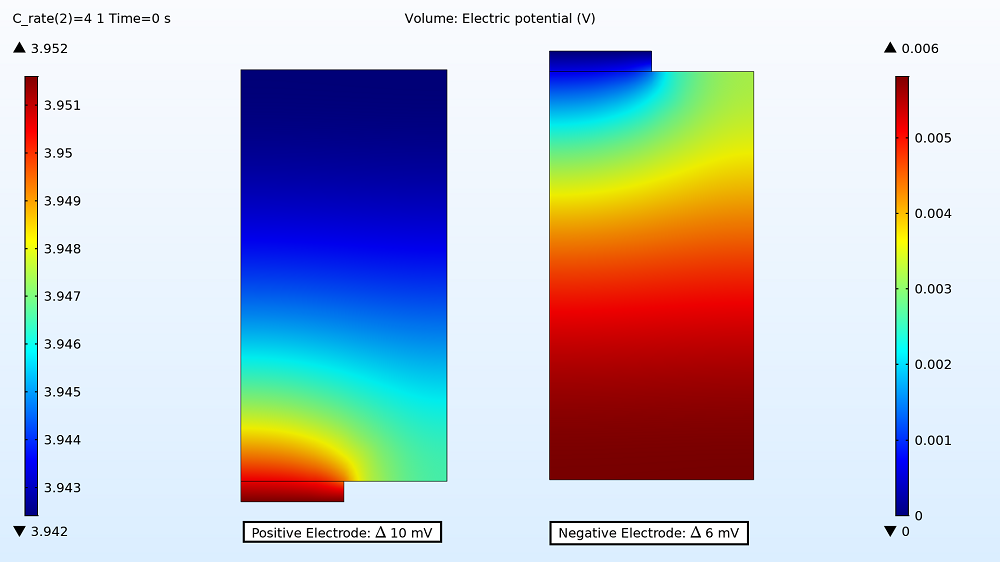
Electric potential distribution in the positive and negative electrodes for the 4C charge.
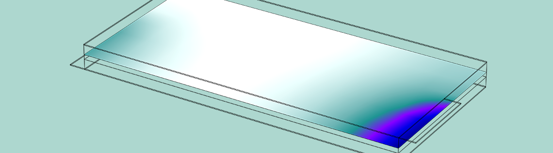
Examining the current distribution in the separator at the start and end of the charging period can also provide insight into the instantaneous electrode utilization. For the 4C charge rate, the relative current density is higher near the two tabs at the beginning, but by the end, the density is higher in the middle, varying by ~6%. As for the 1C charge rate, the variation is once again smaller (1%).
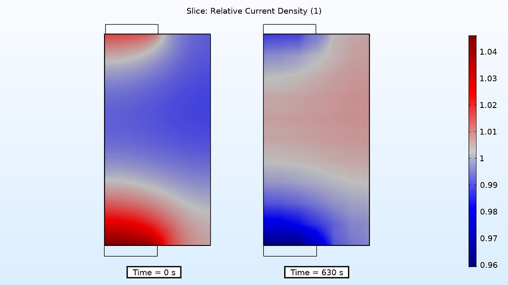
Current distribution in the separator at the start (left) and end (right) of the 4C charging period.
Lastly, you can visualize the relative electrode utilization for the entire charge period. As expected, the utilization is localized at the tabs for the higher currents. The active material is consumed faster at the 4C charge rate near the current collector tabs than in the middle section of the battery assembly. For the faster charge time, the utilization varies by ~2.5% as opposed to only ~1% for the slower charge rate of 1C.
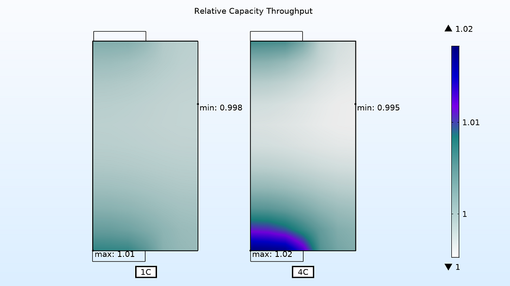
Electrode utilization for 1C (left) and 4C (right) charge rates.
By using simulation to gain insight into the electrode utilization of a battery, engineers could alter the design for a certain operation. For instance, the utilization can be further analyzed by positioning the tabs in different locations or by adjusting the dimensions of the electrode and current collectors to determine how they affect the current distribution at higher C rates.
Next Steps
Try modeling a large-format Li-ion battery pouch cell by clicking the button below. Once in the Application Gallery, you can download the tutorial documentation and the MPH-file.
To learn more about modeling lithium-ion batteries, check out the following blog posts:


Comments (2)
shahriar mostufa
May 12, 2020Thanks a lot
Heri Rustamaji
March 17, 2023Thank you very much.
In thermal analysis of pouch cell, what is the Heat source? Is it just from power dissipation from active material or could we include the ohmic/Joule heating source.